Page 2-72
G1000 Nav III Line Maintenance Manual
Rev. L
190-00352-00
2.7.6
Main Battery Ammeter Calibration Procedure
Perform the following to calibrate the main battery current indication (ammeter) after the 0563.06 software is
loaded:
1.
Ensure all aircraft switches are in the off position and all circuit breakers are IN.
2.
Disconnect the J2 connector at the J-Box.
3.
Using a power supply with an ammeter apply 28.5V to any pin on the J2 connector (to apply power to the
current shunt inside J-Box). Reference the power supply to aircraft ground (GN002).
4.
While pressing and holding the enter (ENT) button on the PFD, apply power to the essential bus by
turning the S BATT switch to ARM. Release the ENT button after the words “INITIALIZING
SYSTEM” appear on the PFD. This will put the PFD in configuration mode.
5.
Keep all other switches OFF.
6.
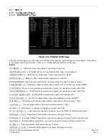
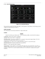
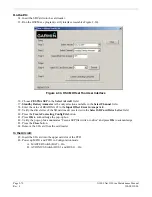
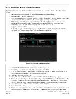
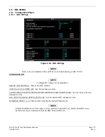
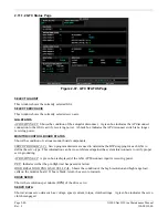
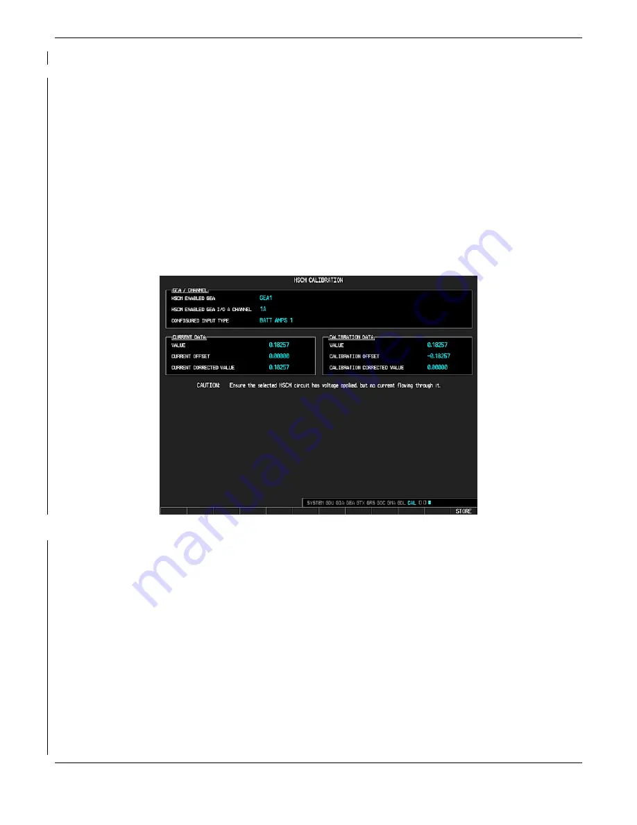
On the PFD navigate to the "CAL" page group using the FMS outer knob. Navigate to the "HSCM
CALIBRATION" page, shown in Figure 2-32, using the FMS inner knob.
Figure 2-32. HSCM Calibration Page
7.
The HSCM ENABLED GEA I/O A CHANNEL needs to stay on 1A.
8.
Press softkey 2 (second from the left), 3, 4, 5 in sequence on the PFD.
9.
Verify that the power supply ammeter shows no current flow. During this calibration procedure 28.5V
needs to be applied to the shunt, but no current can flow through it.
10.
Press the STORE softkey on the PFD.
11.
Select YES and press the ENT button when the “Calibrate HSCM offset?” message appears.
12.
Wait for the GEA to configure. When the GEA configuration is COMPLETE press the ENT button. The
CURRENT CORRECTED VALUE should go to approximately zero. The CURRENT CORRECTED
VALUE corresponds to what the user sees on the G1000 ammeter when powered up in normal mode.
13.
Turn S BATT switch to OFF and return aircraft to normal configuration.
14.
Charge the standby battery.
15.
Perform an extended ground run to see if the main battery ammeter indication is fixed. If the indication is
fixed we will get the official approval put together via Engineering Order (EO) to allow flight of that
Summary of Contents for G1000 NAV III
Page 1: ...190 00352 00 March 2008 Rev L G1000 NAV III LINE MAINTENANCE MANUAL ...
Page 28: ...Page 1 18 G1000 Nav III Line Maintenance Manual Rev L 190 00352 00 Blank Page ...
Page 120: ...Page 2 92 G1000 Nav III Line Maintenance Manual Rev L 190 00352 00 Blank Page ...
Page 184: ...Page 6 6 G1000 Nav III Line Maintenance Manual Rev L 190 00352 00 Blank Page ...
Page 248: ...Page B 34 G1000 Nav III Line Maintenance Manual Rev L 190 00352 00 Blank Page ...

