Page 4-2
G1000 Nav III Line Maintenance Manual
Rev. L
190-00352-00
NOTE
If replacing the PFD with a new, repaired, or exchanged GDU, the new GDU must be placed in
the MFD loaction and the system files loaded. Move the GDU to the PFD location in the aircraft
panel (this step is necessary in order that calibration and other configuration data residing in the
config module is not deleted).
Continue to Section 4.1.12
Displays with GDU Backup Cap Test Software Installed
If a GDU has had the GDU Backup Cap Test Software (006-B0380-15) installed (Section 6), the correct software
files must be installed to return the GDU to the correct configuration. Reloading Jeppesen aviation database files
are not necessary.
Continue to Section 4.1.1.
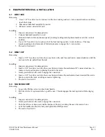
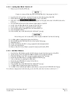
4.1.1
GDU Software
1.
Remove the Supplemental database card from the bottom slot of each GDU.
2.
Insert the Nav III airframe specific G1000 Software Loader Card into top slot of unit replaced.
3.
Power on the MFD and PFD in Configuration mode.
4.
Press the ENT key at “DO YOU WANT TO UPDATE SYSTEM FILES?” prompt.
5.
Confirm update completion.
6.
Confirm correct software part number and software version on the SYSTEM STATUS page.
7.
Power off the MFD and PFD.
8.
Power on the MFD and PFD in normal mode.
9.
Power off the MFD and PFD.
10.
Reinstall the Supplemental database card in the bottom slot of each GDU.
For software/configuration troubleshooting see Section B.4, otherwise continue to Section 4.1.2.
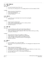
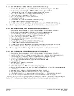
4.1.2
GDU Configuration
GDU software version 6.01 and earlier
No configuration is required. Configuration and lighting settings are automatically updated. However, the
configuration procedure is provided for instances where re-loading the configuration files may be appropriate.
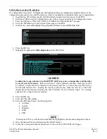
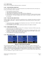
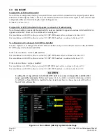
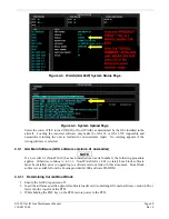
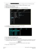
1.
Insert the Nav III airframe specific G1000 Software Loader Card into top slot of the PFD.
2.
Power both MFD and PFD on in Configuration mode.
3.
Press the CLR key at “DO YOU WANT TO UPDATE SYSTEM FILES?” prompt.
4.
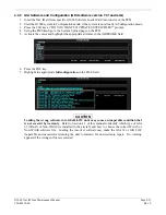
Using the FMS knob go to the Configuration Upload page on the PFD.
5.
Activate the cursor and highlight the appropriate file in the FILE field.
6.
Press the ENT key.
7.
Highlight ‘AIRFRAME’ in the SECTION field.
8.
Press the LOAD softkey.
9.
Select YES and press the ENT key to acknowledge the prompt.
10.
Monitor the status of the upload. When the upload is finished, press the ENT key to acknowledge the
confirmation.
11.
Highlight ‘SYSTEM’ in the SECTION field and repeat steps 8 through 10.
12.
Highlight ‘MANIFEST’ in the SECTION field and repeat steps 8 through 10.
13.
Highlight ‘MFD1’ in the SECTION field and repeat steps 8 through 10.
14.
Highlight ‘PFD1’ in the SECTION field and repeat steps 8 through 10.
15.
View the SUMMARY field and ensure that the load is ‘complete’, then de-activate the cursor.
16.
Confirm correct software part number and software version on the SYSTEM STATUS page.
17.
Some instances may require the user to re-enter the aircraft registration number. Refer to Section B.2.1
for instructions on aircraft registration number entry.
For software/configuration troubleshooting see Section B.4, otherwise continue to Section 4.1.3.
Summary of Contents for G1000 NAV III
Page 1: ...190 00352 00 March 2008 Rev L G1000 NAV III LINE MAINTENANCE MANUAL ...
Page 28: ...Page 1 18 G1000 Nav III Line Maintenance Manual Rev L 190 00352 00 Blank Page ...
Page 120: ...Page 2 92 G1000 Nav III Line Maintenance Manual Rev L 190 00352 00 Blank Page ...
Page 184: ...Page 6 6 G1000 Nav III Line Maintenance Manual Rev L 190 00352 00 Blank Page ...
Page 248: ...Page B 34 G1000 Nav III Line Maintenance Manual Rev L 190 00352 00 Blank Page ...

