G1000 Nav III Line Maintenance Manual
Page 4-7
190-00352-00
Rev.
L
4.2.4
GMA Testing
If unit is removed or replaced the following tests are recommended:
4.2.4.1
Intercom System (ICS) Check
Except for marker beacon operation, an in-aircraft checkout may be performed in the aircraft on the ramp with
known good microphone, headset, and speaker.
1.
Plug in headsets at each ICS position.
2.
Ensure that the MAN SQ button is off (no light).
3.
Adjust volume for each position and verify that the ICS is working properly.
4.
Check Pilot and Copilot ICS positions for isolation and proper operation of volume and squelch controls.
5.
Press the PA key. Verify that microphone audio is heard over the speaker when the Push-To-Talk (PTT)
key is pressed.
4.2.4.2
Transceiver Operational Check
Perform a ramp test radio check by exercising the installed transceivers, microphone, microphone key and audio
over the headphones and speaker. Verify that communications are clear and PTT operation is correct for each
pilot position.
1.
Select the audio source corresponding to each installed avionics unit (i.e. NAV1, NAV2, COM1, COM2)
and check for audio over the headsets.
2.
Press the SPKR key and verify that the selected audio is heard over the speaker, if installed.
4.2.4.3
Failsafe Operation Check
1.
Turn the GMA 1347 off by pulling the GMA 1347 circuit breaker. This directs all COM 1 phone audio,
MIC audio and MIC key to the pilot’s position.
2.
Check the failsafe operation by exercising the COM 1 microphone, microphone key and audio over the
headphones. All volume control for the COM audio should be through the PFD/MFD volume control.
Verify proper operation of COM 1 using the failsafe operation.
3.
Close the GMA 1347 circuit breaker to continue testing.
4.2.4.4
Marker Beacon Test
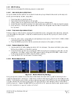
Figure 4-1. Marker Beacon Symbology
Using a ramp tester, simulate the outer marker, middle marker and inner marker signals by following the test
equipment manufacturer’s instructions. Verify that each marker audio signal is present over the headphones and
speaker. Verify that the outer, middle, and inner annunciations appear on the PFD when the corresponding signal
is applied. Marker beacon annunciations appear at the upper left corner of the altitude indicator on the PFD as
shown in Figure 4-1. Operate the MKR MUTE key on the GMA 1347 and ensure that the audio signal is muted.
If no other maintenance is required, continue to Section 5.
Summary of Contents for G1000 NAV III
Page 1: ...190 00352 00 March 2008 Rev L G1000 NAV III LINE MAINTENANCE MANUAL ...
Page 28: ...Page 1 18 G1000 Nav III Line Maintenance Manual Rev L 190 00352 00 Blank Page ...
Page 120: ...Page 2 92 G1000 Nav III Line Maintenance Manual Rev L 190 00352 00 Blank Page ...
Page 184: ...Page 6 6 G1000 Nav III Line Maintenance Manual Rev L 190 00352 00 Blank Page ...
Page 248: ...Page B 34 G1000 Nav III Line Maintenance Manual Rev L 190 00352 00 Blank Page ...


