Page 4-38
G1000 Nav III Line Maintenance Manual
Rev. L
190-00352-00
4.6.4
GEA Testing
If unit is removed or replaced the following tests are recommended:
Each GEA 71 sensor input must be checked with the aircraft engine off. Verify all engine information systems
are valid on the MFD, and no GEA 71 related alerts appear on the PFD. Exercise and test all discrete, analog,
and/or digital inputs and check for appropriate responses.
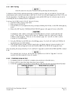
With the STBY BATT CB pulled, check to see that the STBY BATT S current from the bottom right corner of
the EIS strip on the MFD is indicating 0.0 amps. No other maintenance is required when the indication is 0.0. If
the STBY BATT current is indicating anything other than 0.0 amps the GEA 71 Standby Battery High-Side
Current Monitor Calibration procedure will need to be performed. See Section 2.7.5.
If no other maintenance is required, continue to Section 5.
4.7
GTX 33
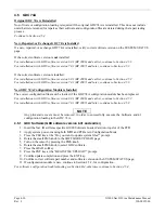
Original GTX 33 Reinstalled
No software or configuration loading is required if the original GTX 33 is reinstalled. This does not include units
that were returned for repair as their software and configuration files are deleted during the repair testing process.
Continue to Section 4.7.4.
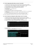
New, Repaired, or Exchange GTX 33 is Installed
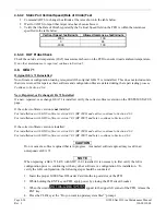
If a new, repaired, or exchange GTX 33is installed, verify the correct software version on the SYSTEM STATUS
page.
If the correct software version is
not
installed:
For installations with GDU software version 6.01 (BP 2006) and earlier, continue to Section 4.7.1.
For installations with GDU software version 7.01 (BP 2007) and later, continue to Section 4.7.3.
If the correct software version is installed:
For installations with GDU software version 6.01 (BP 2006) and earlier, continue to Section 4.7.2.
For installation with GDU software version 7.01 (BP 2007) and later, continue to Section 4.7.3.
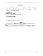
NOTE
If the PFD shows that an upload has stopped before reaching 100%, the G1000 will allow the
installer to restart the upload procedure multiple times until a successful upload is accomplished.
In some instances multiple software upload attempts may be required, if a previous load was
cancelled or corrupt.
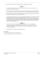
4.7.1
GTX Software (GDU software version 6.01 and earlier)
1.
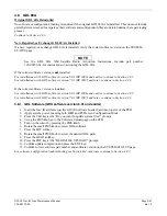
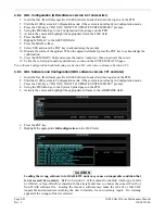
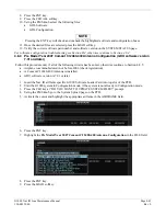
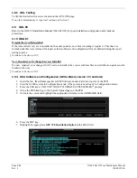
Insert the Nav III airframe specific G1000 Software Loader Card into top slot of the PFD.
2.
Apply system power, insuring both MFD and PFD are in Configuration Mode.
3.
Press the CLR key at the “Do you want to update system files?” prompt.
4.
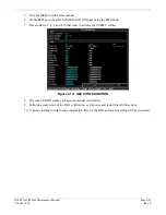
Using the FMS knob to the Software Upload page on the PFD.
5.
Turn on the cursor by pressing the FMS knob.
6.
Rotate the small FMS knob to select GTX software.
7.
Press the LRU softkey.
8.
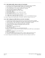
Rotate the small FMS knob to select the desired GTX path.
9.
Press the LOAD softkey.
Summary of Contents for G1000 NAV III
Page 1: ...190 00352 00 March 2008 Rev L G1000 NAV III LINE MAINTENANCE MANUAL ...
Page 28: ...Page 1 18 G1000 Nav III Line Maintenance Manual Rev L 190 00352 00 Blank Page ...
Page 120: ...Page 2 92 G1000 Nav III Line Maintenance Manual Rev L 190 00352 00 Blank Page ...
Page 184: ...Page 6 6 G1000 Nav III Line Maintenance Manual Rev L 190 00352 00 Blank Page ...
Page 248: ...Page B 34 G1000 Nav III Line Maintenance Manual Rev L 190 00352 00 Blank Page ...

