G1000 Nav III Line Maintenance Manual
Page 1-15
190-00352-00
Rev.
L
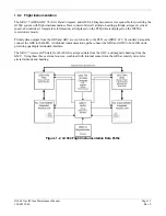
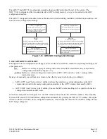
The GRS 77 and GDC 74A configuration modules function differently than the rest of the system. The
GDC 74A’s configuration file is loaded directly to GDC internal memory, a copy is also stored in the GDC
configuration module.
The GRS 77 configuration module stores calibration data recorded during installation calibration procedures, and
does not store configuration settings.
GRS 77
AHRS
GRS 77 Config Module
(Located in GRS backshell connector)
Stores a copy of AHRS/Magnetometer calibration
values that are recorded upon completion of
post-installation calibration procedures.
The GRS 77 stores calibration data internally.
The GRS 77 also stores factory calibration data internally.
Should internal memory or the configuration module fail,
AHRS ouput data flags invalid.
GRS Internal Memory
Contains internal sensor calibration data that is
not installation-specific. Data is stored from
factory calibrations.
GDC 74A
Air Data Computer
GDC 74A Config Module
(Located in GDC backshell connector)
Stores a copy of the GDC 74A configuration file.
The GDC 74A stores the GDC1 configuration file internally.
The GDC 74A also stores factory calibration data internally.
Should internal memory or the configuration module
fail, loss of some or all airdata outputs will result.
GDC Internal Memory
Contains internal sensor calibration data that is
not installation-specific. Data is stored from
factory calibrations.
Figure 1-10. GRS/GDC Configuration Storage
1.4.12
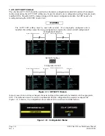
SET>ACTV / ACTV>SET
Throughout various configuration mode pages, there are SET and ACTIVE columns for input/output settings and
other parameters.
SET:
Refers to a setting or group of settings that reside in the PFD’s internal memory and/or master
configuration module (See Figure 1-11).
ACTIVE:
Refers to a current setting stored and used in a LRU. LRUs store the ‘active’ settings within
internal memory.
Data can be manually copied from one column to the other by using the following two softkeys:
•
SET>ACTV (read ‘Set to Active’) softkey: Allows the installer to send the information in the SET
column (data stored in the master configuration module) to the ACTV column (data used by LRU).
•
ACTV>SET (read ‘Active to Set’) softkey: Causes the LRUs current settings to be copied to the master
configuration module as SET items.
In the first example shown in Figure 1-11, the SET columns do not match the ACTIVE columns. The inequality
between SET and ACTIVE indicates a configuration mismatch. By pressing the SET>ACTV softkey, this copies
the SET column to the LRU unit’s configuration memory. The settings then become the ACTIVE settings for the
LRU being configured.
Summary of Contents for G1000 NAV III
Page 1: ...190 00352 00 March 2008 Rev L G1000 NAV III LINE MAINTENANCE MANUAL ...
Page 28: ...Page 1 18 G1000 Nav III Line Maintenance Manual Rev L 190 00352 00 Blank Page ...
Page 120: ...Page 2 92 G1000 Nav III Line Maintenance Manual Rev L 190 00352 00 Blank Page ...
Page 184: ...Page 6 6 G1000 Nav III Line Maintenance Manual Rev L 190 00352 00 Blank Page ...
Page 248: ...Page B 34 G1000 Nav III Line Maintenance Manual Rev L 190 00352 00 Blank Page ...

