background image


Page 2-4 


G1000 Nav III Line Maintenance Manual 

Rev. L 


190-00352-00 

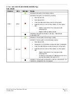
Annunciation 

Associated 

LRU 

Solution 

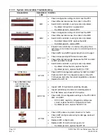
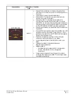
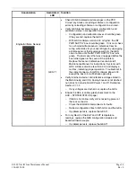
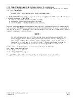
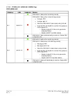
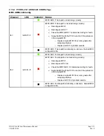
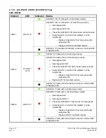
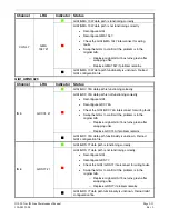
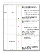
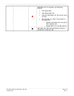
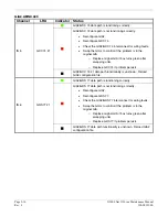
HDG FAIL 


GRS 77 & 

GMU 44 


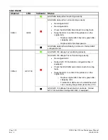
Ensure metal objects (tool boxes, power carts, etc.) are 
not interfering with the magnetometer and aircraft is not in 
hangar, near other buildings, parked over metal drainage 
culverts or on hard surfaces that may contain steel 
reinforcements 


Ensure that a cell phone or a device using cell phone 
technology is not turned on (even in a monitoring state) in 
the cabin. 


Cycle power after moving aircraft away from metal objects 
to determine if metal objects were the source of the 
interference.  Allow up to five minutes for the heading to 
reinitialize. 


Perform a Magnetometer Interference Test to check for 
interference from onboard electrical system components 
(e.g. NAV lights).  Pay particular attention to any new 
electrical devices that have been installed since the 
aircraft was new.  Correct any discrepancies that do not 
allow this test to pass before continuing. 


Ensure GRS 77 and GMU 44 connectors are secure. 


Check the wiring and any inline connectors between the 
GRS and GMU for faults. 


Recalibrate the GMU 44, see Section 4.4.5..2. 


Load configuration files to the PFD, MFD, GIA1, and GIA2 

o


If problem persists replace the GMU 44. 

o


If problem persists, replace the GRS 77.


Summary of Contents for G1000 NAV III

Page 1: ...190 00352 00 March 2008 Rev L G1000 NAV III LINE MAINTENANCE MANUAL ...

Page 2: ...reet Olathe KS 66062 USA Telephone 913 397 8200 Aviation Panel Mount Technical Support Line Toll Free 1 888 606 5482 www garmin com Garmin Europe Ltd Liberty House Bulls Copse Road Hounsdown Business Park Southampton SO40 9RB U K Telephone 44 0 870 8501241 RECORD OF REVISIONS Revision Revision Date Description A 6 24 04 Production release no major changes B 12 15 04 Made minor changes to software ...

Page 3: ... If a test connection to energized equipment is required make the test equipment ground connection before probing the voltage or signal to be tested DO NOT SERVICE ALONE Personnel shall not under any circumstances reach into or enter any enclosure for the purpose of servicing or adjusting the equipment without immediate presence or assistance of another person capable of rendering aid INFORMATION ...

Page 4: ...coated with a special anti reflective coating which is very sensitive to skin oils waxes and abrasive cleaners CLEANERS CONTAINING AMMONIA WILL HARM THE ANTI REFLECTIVE COATING It is very important to clean the lens using a clean lint free cloth and an eyeglass lens cleaner that is specified as safe for anti reflective coatings CAUTION All G1000 screen shots used in this document are only intended...

Page 5: ... 2 3 GMA 1347 2 38 2 4 GIA 63 GIA 63W 2 43 2 5 GRS 77 GMU 44 2 55 2 6 GDC 74A 2 59 2 7 GEA 71 2 61 2 8 GTX 33 2 74 2 9 GDL 69 69A 2 75 2 10 GDL 90 2 78 2 11 GFC 700 BP 2007 and later only 2 79 2 12 Backshell Connectors 2 88 3 EQUIPMENT REMOVAL INSTALLATION 3 1 3 1 GDU 104X 3 1 3 2 GMA 1347 3 1 3 3 GIA 63 GIA 63W 3 1 3 4 GRS 77 GMU 44 3 2 3 5 GDC 74A 3 2 3 6 GEA 71 3 2 3 7 GTX 33 3 3 3 8 GDL 69 69A...

Page 6: ...est 5 2 5 3 Display Failure Test 5 2 5 4 AHRS Air Data Backup Path Test 5 3 5 5 Flight Test 5 3 6 PERIODIC MAINTENANCE 6 1 6 1 Introduction 6 1 6 2 GFC 700 Visual Inspection Procedure 6 3 6 3 GSA 81 Greasing Procedure 6 3 6 4 GSM Slip Clutch Checking and Adjustment Procedure 6 3 6 5 Category A Long Term Power Interrupt Annual Inspection Procedure 6 4 APPENDIX A G1000 PINOUT LIST A 1 A 1 GIA 63 GIA...

Page 7: ... SYSTEM SOFTWARE CONFIGURATION B 1 B 1 Initial Software Configuration Overview B 2 B 2 Final Configuration Items B 24 B 3 Software Configuration Troubleshooting B 26 B 4 System Communication Hierarchy B 27 B 5 Aviation Database B 28 B 6 TAWS Configuration B 29 B 7 SD Card Use B 31 ...

Page 8: ...up 2 6 2 4 AFCS Annunciation Field 2 7 2 5 RS 232 ARINC 429 CONFIG Page 2 19 2 6 GDU STATUS Page 2 20 2 7 GDU TEST Page 2 22 2 8 DIAGNOSTICS Page 2 25 2 9 SERIAL ETHERNET I O Page 2 26 2 10 ALERT CONFIGURATION Page 2 27 2 11 AIRFRAME CONFIGURATION Page 2 27 2 12 GMA CONFIGURATION Page 2 38 2 13 GMA 1347 Data Paths 2 42 2 14 RS 232 ARINC 429 2 43 2 15 CAN RS 485 CONFIGURATION Page 2 44 2 16 GIA I O...

Page 9: ...42 GDU 104X Backshell Connector P10001 2 89 2 43 GRS 77 Backshell Connector P771 2 89 2 44 GDC 74A Backshell Connector P741 2 90 2 45 GDL 69 69A Backshell Connector P691 2 90 2 46 GDL 90 Backshell Connectors 2 90 2 47 GSA 81 Connector P801 2 91 4 1 Marker Beacon Symbology 4 7 4 2 Non WAAS GIA 63 System Status Page 4 8 4 3 WAAS GIA 63W System Status Page 4 9 4 4 System Upload Page 4 9 4 5 AUX GPS S...

Page 10: ... 00352 00 LIST OF TABLES TABLE PAGE 4 1 GRS 77 GMU 44 Calibration 4 21 4 2 Example Magnetometer Interference Test Sequence 4 28 6 1 Long Term Power Interrupt Category B 50 mS Mod Status 6 1 6 2 T206H Slip Clutch Settings 6 3 6 3 T182T Slip Clutch Settings 6 3 ...

Page 11: ...e G1000 system s normal reversionary and configuration modes The configuration mode user interface is described along with a brief summary of configuration mode functionality Section 2 This section contains basic troubleshooting instructions for the G1000 Section 3 This section contains basic removal and replacement instructions for G1000 LRUs Section 4 This section contains basic instructions for...

Page 12: ...rates NAV COM digital audio intercom system and marker beacon controls Manual display reversion is also controlled by the GMA 1347 The GMA 1347 is normally installed between the MFD and PFD The GMA 1347 can also be installed in dual audio panel applications usually paired with a dual PFD setup The GMA 1347 communicates with both GIAs using RS 232 digital interface Software and configuration settin...

Page 13: ... interface GDC 74A The GDC 74A air data computer compiles information from the pitot static system and various outside air temperature OAT and angle of attack AOA sensors The GDC 74A is responsible to provide pressure altitude airspeed vertical speed and OAT information to the G1000 system The GDC 74A communicates with the GIA 63 GIA 63W GDU 104X and GRS 77 using ARINC 429 digital interface Softwa...

Page 14: ...data The GDL 69A is the same as the GDL 69 with the addition of XM Satellite Radio audio entertainment Weather data and control of audio channel and volume is displayed on the GDU 104X MFD via a High Speed Data Bus HSDB Ethernet connection The GDL 69A is also interfaced to the GMA 1347 Audio Panel for amplification and distribution of the audio signal GDL 90 The GDL 90 is a remote mounted product ...

Page 15: ...t board as well as a solenoid and a brushless DC motor The GSA 81 receives serial RS 485 data packets from the GIA 63Ws The GSM 85 servo mount is mounted to the aircraft structure via a custom mounting bracket and is responsible for transferring the output torque of the GSA 81 servo actuator to the mechanical flight control surface linkage GTP 59 The GTP 59 OAT Probe provides outside air temperatu...

Page 16: ...ne Maintenance Manual Rev L 190 00352 00 1 3 G1000 Block Diagrams 1 3 1 Typical System Interconnect Figure 1 1 shows a typical Cessna Nav III G1000 system interconnect Figure 1 1 Typical Cessna Nav III G1000 System Interconnect ...

Page 17: ...ta is displayed on the MFD in reversionary mode Primary data outputs from the GRS and GDC are sent directly to the PFD via ARINC 429 Secondary data paths connect the GRS to the MFD Additional communications paths connect the GRS and GDC to both GIA units providing quadruple redundant interface The GRS 77 receives GPS data from both GIAs airspeed data from the GDC and magnetic heading from the GMU ...

Page 18: ...S 77 AHRS and both displays for processing The GTX 33 Mode S Transponder communicates with both GIAs Transponder data is sent from the GIAs to the PFD The 2 GIA outputs analog HSI signals to the KAP 140 autopilot if equipped In the case of the GFC 700 both of the GIAs communicate to the servos through RS 485 see Figure 1 1 The GMA 1347 Audio Panel controls audio selections and the display reversio...

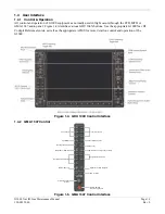
Page 19: ...III Cockpit Reference Guide as well as the appropriate AFMS for more detail on control and operation of the G1000 Figure 1 4 GDU 104X Control Interface 1 4 2 GMA 1347 Control Display Backup Reversionary Button Volume Squelch Control ICS Isolation Digital Recording Playback Manual Squelch Navigation Radio Audio Navigation Radio Audio Marker Beacon Signal Sensitivity Marker Beacon Mute Speaker Passe...

Page 20: ...e FMS knob is the primary control for the G1000 system Operation is similar to the Garmin 400 500 Series units To cycle through different configuration screens To change page groups Rotate the large FMS knob To change pages in a group Rotate the small FMS knob To activate the cursor for a page press the small FMS knob directly in as one would push a regular button To cycle the cursor through diffe...

Page 21: ...4 Audio Alert Configuration Page 5 Software Upload Page 6 Configuration Upload Page 7 System Configuration Page 8 Manifest Configuration Page 1 RS 232 ARINC 429 Config Page 2 GDU Status Page 3 GDU Test Page 4 Serial Ethernet I O Page 5 Alert Configuration Page 6 Airframe Configuration Page 1 RS 232 ARINC 429 Config Page 2 CAN RS 485 Configuration Page 3 GIA I O Configuration Page 4 COM Setup Page ...

Page 22: ...f loading software and configuration files to the system The G1000 Loader Card uses a 128 MB Secure Digital SD data card that contains all necessary files to load software and configuration settings to all G1000 LRUs Nearly all software and configuration parameters are pre determined by Garmin and or Cessna During removal and replacement of LRUs software and configuration files may need to be relo...

Page 23: ...he GMA 1347 audio and serial communications settings GTX1 This file configures the GTX transponder and serial communications settings GEA1 This file configures GEA 71 engine airframe parameters GDC1 This file configures the GDC 74A air data values GDL69 This file configures the GDL 69A serial communications settings CALIBRATION This file configures calibration values for various analog sensors con...

Page 24: ...s so that the configuration of the system is retained in the aircraft during maintenance Since the G1000 Integrated Flight Deck is installed in a variety of aircraft it is imperative that aircraft specific data be retained at the aircraft level Figures 1 9 and 1 10 show a block diagram of how a typical G1000 system stores configuration settings Figure 1 9 G1000 Configuration Storage ...

Page 25: ...ould internal memory or the configuration module fail loss of some or all airdata outputs will result GDC Internal Memory Contains internal sensor calibration data that is not installation specific Data is stored from factory calibrations Figure 1 10 GRS GDC Configuration Storage 1 4 12 SET ACTV ACTV SET Throughout various configuration mode pages there are SET and ACTIVE columns for input output ...

Page 26: ... improperly configured unit is installed this softkey causes the wrong configuration to replace the correct aircraft configuration Master Configuration Module LRU Memory Master Configuration Module LRU Memory Master Configuration Module LRU Memory Master Configuration Module LRU Memory Configuration Mismatch SET ACTV Softkey Configuration Correct Figure 1 11 SET ACTV Feature In most cases when a s...

Page 27: ...g 0 32 Volts DC 2 Phillips Screwdriver 3 32nd inch Hex Tool Digital Level with 0 25 degrees of accuracy capability VHF NAV COM ILS ramp tester Transponder ramp tester including Mode S capability for Mode S transponder equipped aircraft Air Data Test Set ADTS capable of simulating altitude up to the aircraft s service ceiling GPS indoor repeater if outside GPS signals cannot be acquired Headset Mic...

Page 28: ...Page 1 18 G1000 Nav III Line Maintenance Manual Rev L 190 00352 00 Blank Page ...

Page 29: ...d Failure to reload the optional configuration files may deactivate the equipment Be sure to note any optional equipment installed by pre inspection or by logbook entry before loading PFD MFD and or GIA 1 2 configuration files 2 1 G1000 Alerting System 2 1 1 System Annunciations A red X through a display field such as Com frequencies Nav frequencies or engine data indicates that display field is n...

Page 30: ...nd cable Check Ethernet interconnect between the PFD and GIA1 or MFD and GIA2 for faults Switch GIA1 and GIA2 to verify location of problem o If problem follows the GIA replace the GIA o If problem persists replace the MFD or PFD XPDR FAIL GTX 33 Check GTX 33 configuration settings for GIA1 and GIA2 Perform a SET ACTV configuration reset on the GTX Config page and verify the aircraft registration ...

Page 31: ...eled and the PITCH ROLL OFFSET procedure performed Ensure aircraft battery is mounted securely if located near the GRS 77 Ensure GPS has acquired at least four satellites has a 3D navigation solution and a DOP of less than 5 0 This is particularly important for an ATTITUDE FAIL that appears during ground operation only Perform an Engine Run Up Test to check if engine vibration is causing the GRS 7...

Page 32: ...ts to determine if metal objects were the source of the interference Allow up to five minutes for the heading to reinitialize Perform a Magnetometer Interference Test to check for interference from onboard electrical system components e g NAV lights Pay particular attention to any new electrical devices that have been installed since the aircraft was new Correct any discrepancies that do not allow...

Page 33: ...ore the box turned green is the cause of the problem Replace that sensor reference Cessna Aircraft Maintenance Manual for instructions Systems with GDU software versions less than 4 00 will display a red box indicating proper operation Troubleshoot in the same manner as for GDU software above 4 00 except the box color will behave oppositely Verify internal external and reference voltages listed in...

Page 34: ...e operator and technician System messages are normally presented on the PFD and can be viewed by pressing the ALERTS softkey This section provides a listing of possible messages alerts and annunciations Aircraft specific alerts are not covered in this manual 2 1 3 System Status Page MFD Normal Mode Figure 2 3 System Status Page AUX Group The AUX SYSTEM STATUS page on the MFD provides LRU health st...

Page 35: ...e the overall status and condition of the G1000 system on the AUX System Status page on the MFD Any alert messages annunciations or other abnormal behaviors should be noted in an effort to pinpoint the fault More detailed system troubleshooting for a red AFCS or red PFT annunciator is contained in Section 2 11 2 1 4 1 Annunciations and Alerts The GFC 700 AFCS Annunciation field is located above th...

Page 36: ...ion 2 11 for further troubleshooting Pitch Axis Failure Pitch Trim Axis Failure Roll Axis Failure Check the AUX SYSTEM STATUS page to see if the servo is online green check Check that the affected servo is receiving power Check the servo wiring and connector Ensure PTRM switches are not stuck If failure condition still exists remove and replace the affected servo Elevator Mistrim Down Elevator Mis...

Page 37: ...so that for intermittent failures the message would remain at the end of the flight to alert maintenance crew Also this keeps the crew from having to acknowledge message repeatedly in the case of intermittent failures NOTE For GDU software version prior to 7 01 the data path boxes may not be present on the GDU and GIA config pages Troubleshooting failed path messages will require manually checking...

Page 38: ...PFD if box turns green after swapping displays o Replace GRS 77 if problem remains IN 1 GRS 77 1 PFD1 GRS 77 data path functionality is unknown Reload PFD configuration file PFD1 GDC 74 data path is functioning correctly PFD1 GDC 74 data path is not functioning correctly Reconfigure PFD1 Reconfigure GDC 74A Check the PFD1 GDC 74 interconnect wiring for faults Swap the PFD with the MFD to confirm i...

Page 39: ...ginal MFD if box turns green after swapping displays o Replace GRS 77 if problem remains IN 1 GRS 77 1 MFD1 GRS 77 data path functionality is unknown Reload MFD configuration file MFD1 GDC 74 data path is functioning correctly MFD1 GDC 74 data path is not functioning correctly Reconfigure MFD1 Reconfigure GDC 74A Check the MFD1 GDC 74 interconnect wiring for faults Swap the MFD with the PFD to con...

Page 40: ...ly GIA1 GTX 33 data path is not functioning correctly Reconfigure GIA1 Reconfigure GTX 33 Check the GIA1 GTX 33 interconnect wiring for faults Swap the GIA s to confirm if the problem is in the original GIA o Replace original GIA if box turns green after swapping units Replace GTX 33 if problem remains CHNL 5 GTX 33 1 w TIS GIA1 GTX 33 data path functionality is unknown Reload GIA1 configuration f...

Page 41: ...ly GIA1 GDC 74A data path is not functioning correctly Reconfigure GIA1 Reconfigure GDC 74A Check the GIA1 GDC 74A interconnect for wiring faults Swap the GIA s to confirm if the problem is in the original GIA o Replace original GIA if box turns green after swapping units o Replace GDC 74A if problem remains IN 5 GDC 74 1 GIA1 GDC 74A data path functionality is unknown Reload GIA1 configuration fi...

Page 42: ...configure CO GUARDIAN Option Check the GIA2 CO GUARDIAN interconnect for wiring faults Swap the GIA s to confirm if the problem is in the original GIA o Replace original GIA if box turns green after swapping units Replace CO GUARDIAN if problem persists GIA2 CO GUARDIAN data path functionality is unknown Reload GIA2 configuration file GIA2 GTX 33 data path is functioning correctly GIA2 GTX 33 data...

Page 43: ...gure GIA2 Reconfigure GMA 1347 Check the GIA2 GMA 1347 interconnect wiring for faults Swap the GIA s to confirm if the problem is in the original GIA o Replace original GIA if box turns green after swapping units o Replace GMA 1347 if problem persists GIA1 GMA 1347 data path functionality is unknown Reload GIA2 configuration file ...

Page 44: ...green after swapping units o Replace GDC 74 if problem persists IN 5 GDC 74 1 GIA2 GDC 74 1 data path functionality is unknown Reload GIA2 configuration file GIA2 GRS 77 data path is functioning correctly GIA2 GRS 77 data path is not functioning correctly Reconfigure GIA2 Reconfigure GRS 77 Check the GIA2 GRS 77 interconnect for wiring faults Swap the GIA s to confirm if the problem is in the orig...

Page 45: ...blem persists CHNL 1 GEA1 GIA1 GEA data path functionality is unknown Reload GIA1 configuration file GIA1 GFC 700 data path is functioning correctly GIA1 GFC 700 data path is not functioning correctly Reconfigure GIA1 Reload GFC 700 Installation configuration files if equipped Check the GIA1 GSA servo interconnects for wiring faults Swap the GIA s to confirm if the problem is in the original GIA o...

Page 46: ...GEA1 GIA2 GEA data path functionality is unknown Reload GIA2 configuration file GIA2 GFC 700 data path is functioning correctly GIA2 GFC 700 data path is not functioning correctly Reconfigure GIA2 Reload GFC 700 Installation configuration files if equipped Check the GIA2 GSA servo interconnects for wiring faults Swap the GIA s to confirm if the problem is in the original GIA o Replace original GIA...

Page 47: ...or a particular installation and are loaded from the G1000 Loader Card The MFD 1 and PFD 1 configuration files contain the settings shown at this page If the ACTIVE column does not match the SET column reload PFD MFD configuration files from the loader card SELECT UNIT This window shows the currently selected GDU display RS 232 This window shows active RS 232 configuration settings for currently s...

Page 48: ...X s RS 232 channel A green box indicates the RS 232 loopback tests passed A red or black box indicates it may not be used or a wiring fault is present IRDA Indicates status of GDU 104X IrDA infrared port Used for Garmin testing it is not activated at this time ETHERNET 4 Indicates status of GDU 104Xs Ethernet channel 4 Used for Garmin testing it is not activated at this time ANALOG PHOTOCELL A B S...

Page 49: ...k Black PFD 1 Green Black Black PFD 2 RVRSNRY MODE 1 2 Shows the current status of the reversionary modes Reversionary Mode 1 is activated by the GMA 1347 reversion button Reversionary Mode 2 is activated by a second GMA 1347 if installed Reversionary 1 input is a ground on Pin 58 reversionary 2 input is a ground on Pin 15 SPARE INPUT A green box indicates Pin 14 is grounded This input should have...

Page 50: ...s value shown Not useful for troubleshooting CRNT PWM Shows percentage of current pulse width modulation to backlight bulbs Value is between 0 and 10 000 showing the percentage of the maximum allowable current to the backlight Not useful for troubleshooting TOGGLE PWM TO MANL Allows the technician to manually adjust the display brightness TOGGLE CCFT OFF Allows the technician to turn off the backl...

Page 51: ...MP 1 2 Shows the internal temperature of the GDU expressed in degrees Celsius TEST IIC EEPROM Shows the condition of the GDU configuration module EEPROM chip located in the backshell connector It should be green for the PFD and red for the MFD If it is red on the PFD check configuration module wiring and pins for damage before replacing the configuration module DATACARD CHKSUM 1 2 Requires the use...

Page 52: ... green box indicates Pin 53 54 is grounded These inputs should have a black box if either box is green check for connector miswiring or a bent pin FPGA Shows the condition of the GDU FPGA processor If it does not pass the unit may not initialize SYS ID 1 2 3 Shows the current system ID assigned to the display Green indicates that the System ID pin is strapped to ground Black indicates that the Sys...

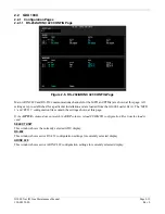
Page 53: ...00 Nav III Line Maintenance Manual Page 2 25 190 00352 00 Rev L 2 2 1 4 DIAGNOSTICS Page Figure 2 8 DIAGNOSTICS Page The DIAGNOSTICS Page is a display only page this page is protected and cannot be changed ...

Page 54: ...nit rejection If there are a substantial growing number of errors logged it indicates an Ethernet communication issue Use the FMS knob to check all three Ethernet ports Generally you should see a continually increasing number in the RCV GOOD FRAMES and XMT GOOD FRAMES to show Ethernet communications are ok This page is protected and cannot be changed If the number of errors are continually increas...

Page 55: ...RATION Page displays all available alerts and what triggers them This page is protected and cannot be changed 2 2 1 7 AIRFRAME CONFIGURATION Page Figure 2 11 AIRFRAME CONFIGURATION Page The AIRFRAME CONFIGURATION Page displays the airframe configuration parameters for instruments airspeed bugs and other items This page is protected and cannot be changed ...

Page 56: ...rt before resetting breaker Ensure circuit breakers have not failed and power wire connections are secure Switch MFD and PFD o If problem follows unit replace the display Please note the position it failed in PFD or MFD o If problem does not follow unit troubleshoot aircraft wiring for fault SD card is stuck in GDU DO NOT insert the screwdriver any length into the card slot DO NOT pry against the ...

Page 57: ...play Display will not track dimmer bus Keyboard will not track dimmer bus Check display lighting settings on the Main Lighting page system group page 3 Check presence or integrity of pin 59 J10001 Check dimmer bus to verify voltage refer to the airframe specific maintenance manual for troubleshooting Switch MFD and PFD o If problem follows unit replace the display Display delaminating Replace GDU ...

Page 58: ... PFD MFD1 DB ERR MFD1 airport terrain database error exists The MFD has encountered an error in the terrain database Confirm datacard is inserted properly Reload airport terrain database o If unable replace supplemental datacard o If problem persists replace the MFD PFD1 DB ERR PFD1 airport terrain database error exists The PFD has encountered an error in the terrain database Confirm datacard is i...

Page 59: ...p database version mismatch Xtalk is off The PFD and MFD have different basemap versions installed Contact Garmin Technical Support for assistance DB MISMATCH Terrain database version mismatch Xtalk is off The PFD and MFD have different terrain database versions installed Insert two identical version Terrain database cards in the PFD and MFD DB MISMATCH Obstacle database version mismatch Xtalk is ...

Page 60: ...D number will change to a new number when installing a new master config module The old Terrain and other cards will no longer work as they will remain locked to the old System ID number 2 2 4 GDU Cooling Alerts Message Cause Solutions MFD1 COOLING has poor cooling Reducing power usage MFD1 has exceeded it s operating temperature range Check cooling fan and wiring for proper operation if applicabl...

Page 61: ...ify key is stuck if key is stuck the corresponding indicator will be green Exercise suspected stuck key and reset GDU TEST page to see if indicator remains green without pressing the key o If problem persists replace the PFD 2 2 6 Datacard Alerts Message Cause Solutions MFD1 CARD data card has failed MFD1 can not read a datacard Remove and reinsert datacard multiple times to clean card contacts Re...

Page 62: ...fy location of problem o If problem does not persist replace original PFD1 DATA LOST Pilot stored data lost Recheck settings Pilot stored data has been lost If the CLR key was held during a power cycle disregard message Cycle power to PFD1 o Ensure CLR key is not stuck on the GDU TEST page o If problem persists replace PFD1 MFD1 SERVICE needs service Return unit for repair The G1000 has determined...

Page 63: ... to the photocell and observe if the CCFT level rises o If the CCFT level rises disregard the message o If the CCFT level does not rise replace the PFD Replace the PFD If GDU software version is less than 6 01 check config module wiring for faults and replace if necessary o If issue continues replace master config module NOTE New Terrain Obstacle cards Jeppesen Aviation Database and other optional...

Page 64: ...Database and other optional features i e TAWS unlock card will need to be replaced if the master configuration module is changed The G1000 System ID number will change to a new number when installing a new master config module The old Terrain and other cards will no longer work as they will remain locked to the old System ID number TAWS FAIL A TAWS system failure has occurred If message occurred o...

Page 65: ...IA2 Traffic device wiring and connectors for faults If using TIS from the GTX33 check for any other GTX config error messages and correct Replace GTX33 HIGH VOLTS Main M or Essential E Bus voltage has exceeded 32 volts Refer to airframe specific Pilot s Operating Handbook POH CO LVL HIGH Unsafe carbon monoxide level reported by CO Guardian unit Refer to airframe specific Pilot s Operating Handbook...

Page 66: ...ning input volume level PASSENGER VOLUME Not used in SEP installations MASTER VOLUME MIN Not used in SEP installations SPEAKER VOLUME CREW AUDIO Sets the crew audio volume level Speaker volume adjustable range is between 31 and 31 PILOT MIC VOLUME Adjusts Pilot Mic Volume for PA speaker COPILOT MIC VOLUME Adjusts Copilot Mic Volume for PA speaker MASTER SQUELCH SENSITIVITY VALUE Sets the Master Av...

Page 67: ...es the MUSIC 1 channel during ICS activity INTERNAL SIDETONE Causes the audio panel to provide COM sidetone in situations when the GIA radios do not provide sidetone MUTE AUDIO ON TX RX All secondary COM audio is muted upon transmitting over primary COM Upon detection of primary COM transmission all secondary COM is muted ANALOG INSTALL COM 1 and COM 2 are connected using the analog interfaces ins...

Page 68: ...is not active Ensure the marker beacon audio is not active Ensure the ICS squelch is not open o Master squelch level can be adjusted on the GMA CONFIGURATION page for higher noise environments Replace unit only after all possible external sources of noise are eliminated Buttons Do Not Work Some buttons are disabled in the GMA CONFIGURATION page by default This is to remove potential sources of aud...

Page 69: ...eiving power Ensure both GIAs are receiving power Ensure all GDUs are receiving power Ensure the GMA GIA RS 232 data lines are working properly Ensure the GIA GDU Ethernet data lines are working properly o Replace GMA GMA1 CONFIG GMA1 configuration error Config service req d The G1000 has detected a GMA configuration mismatch Load GMA configuration file see Section 4 2 2 o Replace GMA o If problem...

Page 70: ...Manual Rev L 190 00352 00 2 3 4 Backup Path Alerts Message Cause Solutions BACKUP PATH Audio panel using backup data path The GMA 1347 is using a backup RS 232 data path o See Section 2 1 5 2 for troubleshooting Figure 2 13 GMA 1347 Data Paths ...

Page 71: ...ain the settings shown on this page SELECT UNIT This window shows the currently selected GIA 63 GIA 63W unit RS 232 This window shows active RS 232 configuration settings for currently selected GIA ARINC 429 This window shows active ARINC 429 configuration settings for currently selected GIA SOFTKEYS The following softkeys appear at this page SET ACTV See Section 1 4 12 for description ACTV SET Se...

Page 72: ...and GIA 2 configuration files contain the settings shown on this page SELECT GIA UNIT This window shows the currently selected GIA 63 GIA 63W CAN This window shows active Controller Area Network configuration settings for currently selected GIA RS 485 This window shows active RS 485 configuration settings for currently selected GIA CLOCKED DATA INTERFACE This window shows active Clocked Data Inter...

Page 73: ...n on this page SELECT GIA UNIT This window shows the currently selected GIA 63 GIA 63W unit SELECT INPUT OUTPUT This window shows input output type that is displayed for the currently selected GIA Options include Discrete In Discrete Out Analog In Analog Out CONFIGURATION This window shows active I O configuration settings for the currently selected GIA and input output type A green box indicates ...

Page 74: ...election Description 25 0 kHz Selects the traditional 25 kilohertz spacing 760 channel 8 33 kHz Selects 8 33 kilohertz channel spacing required in certain areas of the world SQ 250 Sets the squelch threshold for 25 kHz channel spacing operation May be set to any value between 0 zero and 63 The higher the number the less signal is required to break squelch SQ 833 Sets the squelch threshold for 8 33...

Page 75: ...dication of a failed unit GS STATUS ROM SYN LOCK EEPROM Shows the condition of various Glideslope receiver hardware components Black boxes may indicate the GS is not locked onto valid signals and may not be an indication of a failed unit COM STATUS ROM EEPROM SYN LOCK Shows the condition of various COM transceiver hardware components RX Shows whether or not the GIA 63 GIA 63W COM is currently rece...

Page 76: ...ion Green Valid Analog Calibration OVER TEMP Informs the technician of an over temperature condition on the GIA 63 GIA 63W main board Red Over temperature Green Normal temperature LOW TEMP Informs the technician of a low temperature condition on the main board Red Low temperature Green Normal temperature BKUP CAPS Indicates status of the Backup Capacitor Test A green box indicates the test passed ...

Page 77: ...ned to Garmin for installation of Service Bulletin 0505 2 4 3 GPS Symptom Recommended Action Will not acquire satellites Ensure that a cell phone or a device using cell phone technology is not turned on even in a monitoring state in the cabin Check date and time on Date Time Setup Page o If date and time are incorrect enter the correct date and time Switch GIA1 and GIA2 to verify location of probl...

Page 78: ...1000 has determined COM1 needs service Replace GIA1 COM2 SERVICE COM2 needs service Return unit for repair The G1000 has determined COM2 needs service Replace GIA2 COM1 PTT COM1 push to talk key is stuck The COM1 external push to talk PTT switch is stuck in the enabled or pressed state Press the push to talk switch es again to cycle operation Check push to talk switch es and wiring Check GIA1 GMA ...

Page 79: ...s operating temperature range Check fan wiring and air tubing for proper operation if applicable Replace GIA1 If problem persists contact Garmin Aviation Product Support for assistance COM2 TEMP COM2 over temp Reducing transmitter power GIA2 COM has exceeded its operating temperature range Check fan wiring and air tubing for proper operation if applicable Replace GIA2 If problem persists contact G...

Page 80: ...tion of problem o If problem follows the unit replace GIA o If problem does not follow unit check G S1 antenna and cabling G S2 FAIL G S2 is inoperative The G1000 has detected a failure in G S2 receiver Switch GIA1 and GIA2 to verify location of problem o If problem follows the unit replace GIA o If problem does not follow unit check G S2 antenna and cabling 2 4 9 GPS Related Alerts NOTE Before tr...

Page 81: ...uct Support for assistance GIA2 COOLING GIA2 over temperature GIA2 has exceeded its operating temperature range Check fan wiring and air tubing for proper operation if applicable Replace GIA2 If problem persists contact Garmin Aviation Product Support for assistance 2 4 11 Other GIA Alerts Message Cause Solutions GIA1 CONFIG GIA1 configuration error Config service req d GIA2 CONFIG GIA2 configurat...

Page 82: ...work as they will remain locked to the old System ID number MANIFEST GIA1 software mismatch Communication Halted The system has detected an incorrect software version loaded in GIA 1 MANIFEST GIA2 software mismatch Communication Halted The system has detected an incorrect software version loaded in GIA 2 Load correct software version GIA1 SERVICE GIA 1 needs service Return unit for repair The G100...

Page 83: ... degrees PITCH Pitch value input from GRS 77 expressed in degrees X ACC X Axis acceleration value expressed in m s Y ACC Y Axis acceleration value expressed in m s Z ACC Z Axis acceleration value expressed in m s AIR DATA 1 2 SAT Static Air Temperature measurement input from GDC 74A expressed in degrees Celsius IAS Indicated Air Speed measurement input from GDC 74A expressed in knots TAS True Air ...

Page 84: ...onfiguration module o If problem persists replace the GRS 77 Attitude appears unstable Ensure that a cell phone or a device using cell phone technology is not turned on even in a monitoring state in the cabin Ensure the four GRS 77 mounting screws are tight Finger tight is not sufficient a screwdriver must be used to verify Ensure mounting rack and airframe shelf are secure and all hardware and br...

Page 85: ... not turned on even in a monitoring state in the cabin Check GPS status for GIA 1 and 2 on MFD AUX GPS STATUS page If one or both GPS receivers cannot aquire a position lock see Section 2 4 3 for GPS troubleshooting See Section 2 1 5 2 for data path troubleshooting Replace the GRS 77 AHRS Service AHRS magnetic field model needs updated The AHRS magnetic field model has expired Reference Garmin SB ...

Page 86: ...ubleshooting Figure 2 20 GRS 77 Data Paths 2 5 6 GMU Related Alerts Message Cause Solutions MANIFEST GMU1 software mismatch Communication Halted The system has detected an incorrect software version loaded in the GMU 44 Load correct software version in the GMU 44 HDG FAULT A magnetometer fault has occurred A fault has occurred in the magnetometer Check GMU 44 GRS 77 interconnect for faults Replace...

Page 87: ...instrument is outside limits and recalibrate or replace The GDC is field adjustable see Section 2 6 4 Note Both units may individually be in spec but show a difference in altitude Do not return the GDC to Garmin for service if not outside limits GDC Config file does not load Replace GDC config module o If problem persists replace GDC config module wire harness 2 6 2 GDC 74A Related Alerts Message ...

Page 88: ...DC 74 X Field Calibration Tool T06 A0156 00 to adjust the calibration of GDC 74 X units that have failed the 14 CFR Part 43 Appendix E tests due to altitude drift Both the GDC 74 X Field Calibration Tool software and the GDC 74 X Field Calibration Instructions 190 00303 82 can be downloaded from the Dealer Resource portion of the Garmin website at www garmin com First download the GDC 74 X Field C...

Page 89: ...e RPM D ICE PRESS De Ice system pressure measurement expressed in pounds per square inch PSI FUEL PRESS ENG 1 2 Fuel Pressure measurement expressed in pounds per square inch PSI FUEL QTY RIGHT LEFT Fuel Quantity measurement expressed in gallons GL FUEL FLW ENG 1 2 Fuel Flow measurement expressed in gallons per hour GL HR MAP ENG 1 2 Manifold Air Pressure sensor reading expressed in inches mercury ...

Page 90: ...ion CONFIG Shows status of GEA 71 configuration INT PWR SUPPLY Shows status of the GEA 71 5 10 and 12 sensor power supply voltages If it is red troubleshoot as for Engine Instrument Red X s in Section 2 1 1 1 EEPROM MAIN A B Shows status of internal EEPROM for main I O A and I O B boards RAM ROM XILINX Shows status of internal memory and FPGA RS 485 1 2 Shows status of RS 485 I O channels COM CHAN...

Page 91: ...the technician cannot make changes unless authorized and equipped to do so GEA This window indicates which GEA GEA circuit board and or GEA I O channel is currently selected for display DATA This window shows current configuration settings for the selected inputs outputs in the GEA window SOFTKEYS ANLG CRNT Shows analog current configuration settings ANLG IN Shows analog in configuration settings ...

Page 92: ...der for an open or dead spot Engine instruments are missing on the MFD Clear user data on each GDU by holding down the CLR button while powering on each GDU Keep the other display off while clearing user data Discharged standby battery indication Refer to Section 2 7 5 for the GEA 70 High Side Current Monitor Calibration Procedure 2 7 3 GEA 71 Related Alerts Message Cause Solutions GEA1 CONFIG GEA...

Page 93: ...ual Page 2 65 190 00352 00 Rev L 2 7 4 Backup Path Alerts Message Cause Solutions BACKUP PATH EIS using backup data path The GEA 71 is using a backup RS 485 data path See Section 2 1 5 4 for troubleshooting Figure 2 25 GEA 71 Data Paths ...

Page 94: ... volt cart 2 Arm the STBY BATT Switch and verify the PFD comes on 3 Verify no red X s appear on the engine indicators 4 Verify BUS E Volts shows a minimum of 24 Volts 5 Verify M BUS Volts shows 1 5 Volts or less 6 Turn the MASTER Switch BAT on 7 Turn the AVIONICS Switch BUS 1 and 2 on and verify the MFD comes on On the MFD 8 Using the FMS knob navigate to the AUX SYSTEM STATUS page as shown in Fig...

Page 95: ...elect Aircraft field 19 Standby Battery Ammeter is the only selection available in the Select Channel field 20 Enter 0 0 in the Input Offset Error in Amps field This step will reset any previous calibrations to zero before performing the actual calibration 21 Verify the drive letter of the SD card reader is selected in the Select SD Card Drive Letter field 22 Press the Create Correcting Config Fil...

Page 96: ...ate to the CONFIGURATION UPLOAD page as shown in Figure 2 28 ii Using the FMS knob select the Cessna SEP Offset Error Correction File in the FILE field iii Using the FMS knob highlight GEA 1 in the SELECTION field iv Press the ENT key to start the configuration upload Figure 2 28 CONFIGURATION UPLOAD Page GDU software version 6 01 or earlier ...

Page 97: ...igure 2 29 CONFIGURATION UPLOAD Page GDU software version 7 01 or later 29 Power down PFD1 and MFD1 A AVIONICS Switch BUS 1 and BUS 2 Off B MASTER Switch BAT Off 30 Remove the SD card from the PFD 31 Power up MFD1 and PFD1 in Normal mode A STBY BATT Switch Arm B Ensure STBY BATT CB is open C MASTER Switch BAT On D AVIONICS Switch BUS 1 and BUS 2 On 32 Record the BATT S current in Amps from the bot...

Page 98: ...READING 2 in the Input Offset Error in Amps field 39 Verify the drive letter of the SD card reader is selected in the Select SD Card Drive Letter field 40 Press the Create Correcting Config File button 41 Press OK to acknowledge the pop up box 42 Verify the pop up box annunciates Cessna SEP file written to drive and press OK to acknowledge 43 Press the Close button 44 Remove the SD card from the c...

Page 99: ... bottom corner of the EIS strip reads 0 0 Amps If the BATT S current indication does not read 0 0 repeat procedure ensuring all steps have been followed If the BATT S current indication still does not read 0 0 return the GEA 71 to Garmin for servicing 52 Power down PFD1 and MFD1 A AVIONICS Switch BUS 1 and BUS 2 Off B M ASTER Switch BAT Off 53 Close the STBY BATT CB 54 Turn the STBY BATT switch to...

Page 100: ...o the HSCM CALIBRATION page shown in Figure 2 32 using the FMS inner knob Figure 2 32 HSCM Calibration Page 7 The HSCM ENABLED GEA I O A CHANNEL needs to stay on 1A 8 Press softkey 2 second from the left 3 4 5 in sequence on the PFD 9 Verify that the power supply ammeter shows no current flow During this calibration procedure 28 5V needs to be applied to the shunt but no current can flow through i...

Page 101: ...e airplane will be required CAUTION FLIGHT OF THAT AIRPLANE WITH THE 0563 06 SOFTWARE LOADED IS NOT PERMITTED UNTIL AN ENGINEERING ORDER EO OR SERVICE BULLETIN IS ISSUED TO APPROVE THE SOFTWARE LOAD FOR THAT AIRPLANE 16 Load the original software 0563 03 back on the airplane The instructions for loading the 0563 03 software are included in SB07 34 02 Garmin G1000 System Software Upgrade to Version...

Page 102: ...ew Terrain Obstacle cards Jeppesen Aviation Database and other optional features i e TAWS unlock card will need to be replaced if the master configuration module is changed The G1000 System ID number will change to a new number when installing a new master config module The old Terrain and other cards will no longer work as they will remain locked to the old System ID number MANIFEST GTX1 software...

Page 103: ...e SELECT GDL ANTENNA Selects the GDL antenna ANTENNA GAIN LOWER dB Sets the antenna gain value CABLE LOSS INCLUDING INLINE ATTENUATIONS IF USED NOMINAL dB Sets the inline cable loss attenuation value GDL CONFIGURABLE ATTENUATION dB Sets the desired GDL attenuation value ETHERNET PORT 2 3 4 Enables and or disables the desired Ethernet port NOTE AUDIO RADIO refers to XM audio receiver installed in t...

Page 104: ...dio and weather options Levels 0 and 1 are likely indications of problems with availablity A 204 message in the signal field indicates that signal information has not initialized DIAGNOSTICS For XM use only not useful for troubleshooting QUALITY OF SERVICE Displays the quality of service for the GDL 69 69A TERRESTRIAL ERROR STATUS Displays the terrestrial error status for the GDL 69 69A SATELLITE ...

Page 105: ...r mismatch reload the file noted in the Alert Restart the PFD and MFD in configuration mode and go to the GDL page o Verify unit is active Verify the Signal number is 2 or 3 If it is 0 or 1 check the GDL 69 69A antenna and cabling for faults o Reseat the GDL 69 69A to verify the coax connector is fully seated o If unit is not active contact XM Customer service at 1 800 985 9200 to have a refresh s...

Page 106: ...Solutions GDL 69 FAIL GDL 69 has failed The G1000 has detected a failure in the GDL 69 69A Check GDL 69 69A antenna and cabling Check the GDL 69 69A and MFD interconnect Replace GDL 69 69A Figure 2 35 GDL 69 Data Paths 2 10 GDL 90 Refer to the GDL 90 Installation Manual 560 1049 02 for troubleshooting information ...

Page 107: ...cal to aircraft safety SELECT GIA UNIT This window shows the currently selected GIA CONFIGURATION AP DISC REMOVES FD Autopilot disconnect turns flight director function on or off PITCH SERVO Shows the currently selected pitch servo ROLL SERVO Shows the currently selected roll servo YAW SERVO Shows the currently selected yaw servo PITCH TRIM SERVO Shows the currently selected pitch trim servo ROLL ...

Page 108: ...rd components SERVO PROGRAM 1 3 Servo program discreets are used to determine the HW strapping for each GSA to define the servo type This information can be cross referenced against the system interconnects to verify proper servo grounding AP DISCONNECT A green box is displayed if the GSA AP Disconnect input is receiving power PFT Indicates wether the pre flight test has passed or failed HIGH RES ...

Page 109: ...NOTE Thoroughly understanding the operation of the G1000 system in configuration mode is recommended before starting this procedure To access the GIA and GSA Maintenance Logs perform the following steps 1 Start the G1000 in Configuration mode 2 Use the FMS knob on the PFD to go to the Diagnostics Terminal page in the System group This page allows the technician to view maintenance logs associated ...

Page 110: ... angle has exceeded the engagement limits d Cross Hdg Accel Fail Cross heading acceleration monitor failed e Vert Accel Fail Vertical acceleration monitor failed f Fltrd Cross Hdg Accel Fail Filtered cross heading acceleration monitor failed g Fltrd Vert Accel Fail Filtered vertical acceleration monitor failed h Roll Accel Fail Roll acceleration monitor has failed i Normal Accel Fail Normal accele...

Page 111: ...ernet connection from the PFD to the GIA is functioning PFT Step 4 System initializing verify AHRS monitor This step checks to ensure the AHRS monitor is valid and not reporting an AHRS failure NOTE AHRS monitor will be assumed valid if on the ground Ensure the GRS 77 and GDC 74 are turned on and sending valid data PFT Step 5 System initializing verify configured servos are valid This step checks ...

Page 112: ...8 volts Ensure the autopilot disconnect switch is not pressed PFT Step 14 Verify servo validity This step checks to ensure all servos are online and communicating with valid data Ensure all servos are turned on and communicating PFT Step 15 Verify cross GIA PFT is completed This step checks to ensure the cross side GIA is also on step 14 Cycle power on all servos and GIAs Ensure the PFD and MFD ar...

Page 113: ... internal problem requiring replacement of the servo If the items in the Notes column check out ok replace the servo PFT Faults MONITOR PFT STEP NOTES INTERNAL COMM FAIL This can sometimes be a result of a failure on the other internal servo board check faults on the other processor UNSW POWER INV Check unit power MON SOL PWR ON FAIL Check unit power and AP Disconnect power CTL SOL PWR ON FAIL Che...

Page 114: ...ST FAIL This can sometimes be a result of a failure on the other board check faults on other processor CTL MOT PWR ON FAIL Check unit power and AP Disconnect power MON MOT PWR ON FAIL Check unit power and AP Disconnect power HALL 1 FAIL Check unit power and AP Disconnect power HALL 2 FAIL Check unit power and AP Disconnect power HALL 3 FAIL Check unit power and AP Disconnect power HALL 4 FAIL Chec...

Page 115: ...r to the SERVO box and selecting the servo you need to access using the small FMS knob to activate the drop down list and press the ENT key Be sure to download both the Monitor and Control Logs for that servo 7 Move the cursor to the COMMAND box and select View Maintenance Log in the drop down menu then press the ENT key The error log data will be displayed in the OUTPUT box If you see the more pr...

Page 116: ...15 16 17 18 19 20 21 22 23 24 25 26 27 28 29 30 31 32 33 34 35 36 37 38 39 40 41 42 43 44 45 46 47 48 49 50 51 52 53 54 55 56 57 58 59 60 61 62 63 64 65 66 67 68 69 70 71 72 73 74 75 76 77 78 COM BOARD CONNECTOR P601 COM ANTENNA CONNECTOR COOLING PORT MAIN DISCRETE CONNECTOR P604 MAIN SERIAL CONNECTOR P603 GPS ANTENNA CONNECTOR I O CONNECTOR 2 P606 I O CONNECTOR 1 P605 G S ANTENNA CONNECTOR NAV AN...

Page 117: ...68 69 70 71 72 73 74 75 76 77 78 P3471 P3472 Figure 2 40 GMA 1347 Backshell Connectors 1 2 3 4 5 6 7 8 9 10 11 12 13 14 15 16 17 18 19 20 21 22 23 24 25 26 27 28 29 30 31 32 33 34 35 36 37 38 39 40 41 42 43 44 45 46 47 48 49 50 51 52 53 54 55 56 57 58 59 60 61 62 TOP ANTENNA CONNECTOR BOTTOM ANTENNA CONNECTOR P3301 COOLING PORT Figure 2 41 GTX 33 Backshell Connectors Figure 2 42 GDU 104X Backshell...

Page 118: ...e Manual Rev L 190 00352 00 Figure 2 44 GDC 74A Backshell Connector P741 Figure 2 45 GDL 69 69A Backshell Connector P691 P3 GPS Antenna P4 Top Antenna P5 Bottom Antenna P1 15 Pin P2 37 Pin Cooling Fan Figure 2 46 GDL 90 Backshell Connectors ...

Page 119: ...G1000 Nav III Line Maintenance Manual Page 2 91 190 00352 00 Rev L A B C D E F G H J L M N P R S T U V K Figure 2 47 GSA 81 Connector P801 ...

Page 120: ...Page 2 92 G1000 Nav III Line Maintenance Manual Rev L 190 00352 00 Blank Page ...

Page 121: ... rotate counterclockwise until the unit can be freely pulled from the rack Installing 1 Inspect connector s for damaged pins 2 Insert a 3 32 hex drive tool into the access hole and rotate the mechanism 90 counterclockwise to insure correct position prior to placing the unit in the rack 3 Gently push unit into the rack to engage the connectors 4 Insert a 3 32 hex drive tool into the access hole and...

Page 122: ...embly and pitot static plumbing from unit 3 Remove all Teflon tape or sealing compound Take care not to allow Teflon tape or sealing compound to fall inside unit Installing 1 Inspect connector s and pitot static plumbing for damage 2 Install Teflon tape or sealing compound to pitot static plumbing 3 Connect backshell assembly and pitot static plumbing to the unit 4 Tighten two thumb screws that se...

Page 123: ...ged pins 2 Gently push unit into the rack to engage the connectors 3 Push the GDL 69 69A lever down towards the bottom of the unit avoiding the use of excessive force 4 If lever fails to go down adjust backplate while engaging unit 5 Lock the handle into the GDL 69 69A body and tighten the Phillips screw 6 Proceed to Section 4 8 3 9 GDL 90 Refer to the applicable aircraft maintenance manual for re...

Page 124: ...0 2 De rig the flight control cabling or chain 3 Use a socket or open wrench to loosen and remove the servo attachment bolts 4 Carefully remove the servo mount Installing 1 Follow the installation instructions in the respective servo installation drawing 2 If no other maintenance is to be performed reinstall the servo s per Section 3 10 ...

Page 125: ...ion module is replaced proceed to Section 4 5 6 If master configuration module is replaced a Turn the PFD on in configuration mode By pressing and holding the ENT key while powering the unit b Go to the Configuration Upload Page in the System Page Group c Press the UPDT CFG softkey 7 If the PFD and master configuration module is replaced proceed to Appendix B NOTE If the master configuration modul...

Page 126: ...crew thermocouple from boss on backshell Extract the thermocouple pins from the connector Installing 1 Crimp pins item 2 onto each of the thermocouples wires item 1 Ensure that pre stripped wire length is 1 8 prior to crimping 2 Insert newly crimped pins and wires into the appropriate connector housing location item 4 3 Place thermocouple body item 1 onto the backshell boss item 5 Place the thermo...

Page 127: ...t inserted can become corrupt making them unusable Replacing corrupt cards is not covered under warranty NOTE Refer to the Cessna Maintenance Manual for approved software versions and part numbers NOTE Garmin recommends the use of SanDisk or Toshiba SD cards to load G1000 software and configuration files If software loading problems occur when using another brand of card replace the card with a Sa...

Page 128: ...1 2 4 1 2 GDU Configuration GDU software version 6 01 and earlier No configuration is required Configuration and lighting settings are automatically updated However the configuration procedure is provided for instances where re loading the configuration files may be appropriate 1 Insert the Nav III airframe specific G1000 Software Loader Card into top slot of the PFD 2 Power both MFD and PFD on in...

Page 129: ...ey 7 Highlight the appropriate full configuration in the FILE field CAUTION Loading the wrong software into GIA63 63W units may cause an inoperable condition that is not covered by warranty Refer to Section 4 3 of this manual to identify which type of GIA 63 WAAS or Non WAAS is installed in the aircraft and how to choose the correct WAAS or Non WAAS software file Loading the incorrect software may...

Page 130: ...p this causes the attitude airspeed and altitude fields to be invalid during the first 40 60 seconds of PFD power up Check the PFD and MFD displays for the following 1 Check that all COM NAV display fields are valid in the top corners of the PFD and MFD 2 Check that altitude airspeed vertical speed and OAT fields are valid on the PFD 3 Check that attitude and heading are valid unless an AHRS calib...

Page 131: ...to update system files prompt 4 Using the FMS knob go to the Software Upload page on the PFD 5 Turn on the cursor by pressing the FMS knob 6 Rotate the small FMS knob to select GMA software 7 Press the LRU softkey 8 Rotate the small FMS knob to select the desired GMA path 9 Press the LOAD softkey 10 Press the ENT key at the BEGIN FILE UPLOAD prompt 11 Confirm update completion and press the ENT ke...

Page 132: ... inoperable condition that is not covered by warranty Refer to Section 4 3 of this manual to identify which type of GIA 63 WAAS or Non WAAS is installed in the aircraft and how to choose the correct WAAS or Non WAAS software file Loading the incorrect software may make the GIA 63 or GIA 63W inoperable and necessitate returning the unit to Garmin for non warranty repair No warning appears if the wr...

Page 133: ...OM2 and check for audio over the headsets 2 Press the SPKR key and verify that the selected audio is heard over the speaker if installed 4 2 4 3 Failsafe Operation Check 1 Turn the GMA 1347 off by pulling the GMA 1347 circuit breaker This directs all COM 1 phone audio MIC audio and MIC key to the pilot s position 2 Check the failsafe operation by exercising the COM 1 microphone microphone key and ...

Page 134: ...and later continue to Section 4 3 5 New Repaired or Exchange GIA 63 63W s Installed If a new repaired or exchange GIA 63 GIA 63Wis installed verify correct software version on the SYSTEM STATUS page for both main and GPS If the correct software version is not installed For installations with GDU software version 6 01 BP 2006 and earlier continue to Section 4 3 1 For installations with GDU software...

Page 135: ...re GDU software version 6 01 and earlier NOTE If a new GIA 63 Non WAAS has been installed new serial number the following procedure applies Otherwise continue to 4 3 1 3 Non WAAS GIA v4 01 or later boot block software must be installed prior to upgrading to software versions listed in this document Boot Block software is available from the Cessna provided G1000 software CD ROM 4 3 1 1 Determining ...

Page 136: ...e PFD use the FMS knob to turn to the Software Upload page 10 Use the FMS knob to highlight GIA 6X software 11 Press the LRU softkey and highlight GIA 1 12 Press the ENT key to begin loading software 13 The boot block version should now appear on the MFD 14 If GIA main boot block version is 4 00 or earlier press the CANCEL softkey on the PFD and select YES at the prompt Continue to Section 4 3 1 2...

Page 137: ...lock is loading 11 Confirm update completion and press the ENT key 12 On the MFD use the FMS knob to turn to the System Status page 13 Highlight GIA 1 14 Verify G1000 GIA 6X SYS is being reported in the description field 15 Power down the G1000 16 Remove the GIA 63 boot block version 4 01 loader card form the PFD 4 3 1 3 GIA Main Software 1 Insert the Nav III airframe specific G1000 Software Loade...

Page 138: ...D prompt 9 Confirm update completion and press the ENT key 10 Confirm correct software part number and software version on the SYSTEM STATUS page 11 If the AUDIO software load failed load GIA Boot Block software per 4 3 1 2 For software configuration troubleshooting see Section B 4 otherwise continue to Section 4 3 4 4 3 4 GIA Configuration GDU software version 6 01 and earlier 1 Insert the Nav II...

Page 139: ...Activate the cursor and highlight the appropriate airframe in the AIRFRAME field 6 Press the ENT key 7 Highlight the appropriate full configuration in the FILE field CAUTION Loading the wrong software into GIA63 63W units may cause an inoperable condition that is not covered by warranty Refer to Section 4 3 of this manual to identify which type of GIA 63 WAAS or Non WAAS is installed in the aircra...

Page 140: ... 7 NOTE Optional equipment configuration files must be loaded in order to enable the optional equipment See Appendix B 1 8 for instructions on how to load optional equipment files 4 3 6 Stormscope Configuration If Equipped 1 Select the GIA page group on the PFD The GIA RS 232 ARINC 429 Configuration Page appears by default 2 Select the appropriate GIA to be configured Refer to aircraft specific in...

Page 141: ...inutes of startup provided the aircraft is outside or indoors with a GPS repeater NOTE In some rare instances when the GPS receiver is taking longer than normal to acquire a date and or time change may be required This can be done on the DATE TIME SETUP page in configuration mode Select the satellite status page on the MFD 3rd page in AUX group Two softkeys on the bottom of the display allow the u...

Page 142: ...M channel spacing from 25 kHz to 8 33 kHz 12 Go back to the 3rd AUX page 13 Select 121 185 MHz on the No 1 COM transceiver GIA1 14 Transmit for a period of 35 seconds while monitoring GPS 1 signal strength levels 15 During the transmit period verify that the GPS INTEG flag does not come into view on the PFD and verify that GPS 1 does not lose a 3 D navigation solution on the MFD 16 Repeat steps 14...

Page 143: ... original GMU 44 is reinstalled no software loading is required Continue to Section 4 4 5 New Repaired or Exchange GMU 44 is Installed If the GMU 44 was replaced with a new repaired or exchange unit verify correct software version on the SYSTEM STATUS page If the correct software version is not installed For installations with GDU software version 6 01 BP 2006 and earlier continue to Section 4 4 2...

Page 144: ...on B 4 otherwise continue to Section 4 4 5 4 4 3 GRS 77 Software GDU software version 7 01 and later 1 Insert the Nav III airframe specific G1000 Software Loader Card into top slot of the PFD 2 Start the G1000 system in Configuration mode if the system is not already in Configuration mode 3 Press the CLR key at DO YOU WANT TO UPDATE SYSTEM FILES prompt 4 Using the FMS knob go to the System Upload ...

Page 145: ...art the G1000 system in Configuration mode if the system is not already in Configuration mode 3 Press the CLR key at DO YOU WANT TO UPDATE SYSTEM FILES prompt 4 Using FMS knob go to the SYSTEM UPLOAD page on the PFD 5 Activate the cursor and highlight the appropriate airframe in the AIRFRAME field 6 Press the ENT key 7 Highlight the appropriate full configuration in the FILE field CAUTION Loading ...

Page 146: ...nots the aircraft is considered not moving and attitude heading will become valid 2 If valid 3D GPS data is not available but valid true airspeed is less than 30 knots the aircraft is considered not moving and attitude heading will become valid 3 If both 3D GPS and true airspeed are unavailable attitude heading will not become valid No configuration is required for the GRS 77 unless the mounting b...

Page 147: ...Required Continue to Section 4 4 4 Replaced the GRS 77 and loosened mounting rack bolts X X X Replaced the GRS 77 Configuration Module X X X Replaced the GMU 44 new serial number X GMU 44 was removed and reinstalled same serial number None Required Continue to Section 4 4 4 Table 4 1 GRS 77 GMU 44 Calibration 4 4 5 1 Procedure A1 Pitch Roll Offset Calibration Figure 4 6 Pitch Roll Offset ...

Page 148: ...nsure that the No 1 GRS 77 is selected d Select PITCH ROLL OFFSET then press the ENT key e Follow the checklist items displayed on the PFD and press the ENT key as each one is completed or confirmed When the CALIBRATE field is blinking press the ENT key to begin the procedure f After several seconds a new checklist appears in the lower half of the PFD Press the ENT key as each item is confirmed Wh...

Page 149: ...e Taxi the aircraft to a compass rose Ensure that there are no nearby magnetic materials on or near the perimeter of the compass rose If unavoidable maneuver the aircraft to keep the magnetometer from passing within twenty feet 6 1 meters of such objects Additionally ensure that vehicles or other aircraft are adequate distance away from the aircraft under test At the compass rose align the aircraf...

Page 150: ... in executing smooth accurate turns the PFD may incorrectly interpret a station and instruct to HOLD POSITION prior to full completion of a 30 turn If this scenario is encountered it is best for the operator to ignore the HOLD POSITION command and instead use outside references to complete the approximate 30 turn Instead of using the PFD instruction to turn as a real time indication of when to tur...

Page 151: ... back to idle over a period of 2 4 minutes 3 When the operator has completed the engine run up and the engine is back to an idle setting press the ENT key to indicate that the process is complete When this is done the TEST COMPLETE field stops blinking 4 The PFD informs the operator if the installation has passed or failed the vibration test If the test fails the specific measurements causing the ...

Page 152: ...ctor not firmly attached to unit g Cabling leading to GRS77 or GMU44 not firmly secured to supporting structure h An engine propeller that is significantly out of balance In some aircraft attempting the engine run up test on a day with very strong and or gusty winds may cause the test to occasionally fail However windy conditions should not be taken as evidence that the test would pass in calm con...

Page 153: ... the operation of the GMU 44 magnetometer which directly impacts the determination of attitude and heading by the GRS 77 AHRS Calibration Procedures A 1 through D are not required prior to this execution of this procedure 1 Initiate the AHRS magnetometer interference test procedure by performing the following steps a Enter Configuration Mode and go to GRS GMU Calibration page as shown in Figure 4 ...

Page 154: ... Speed brake up 1 50 Speed brake down 2 00 Navigation lights on 2 10 Navigation lights off 2 20 Landing lights on 2 30 Landing lights off 2 40 Taxi lights on 2 50 Taxi lights off 3 00 Landing Taxi lights on 3 10 Landing Taxi lights off 3 20 Strobes on 3 30 Strobes off 3 40 Recognition lights on 3 50 Recognition lights off 4 00 Turn on all wing tip lights simultaneously typically will include navig...

Page 155: ...urce of magnetic interference is identified and remedied When the magnetometer interference test fails record the three magnetometer maximum deviation values and their corresponding timestamps Any maximum deviation value greater than 2 5 milliGauss indicates a problem that must be resolved Compare the corresponding timestamps with the prepared test sequence to identify which action produced the pr...

Page 156: ...orrect configuration files must be loaded if the GDC 74A configuration module has been replaced For installations with GDU software version 6 01 BP 2006 and earlier continue to Section 4 5 2 For installations with GDU software version 7 01 BP 2007 and later continue to Section 4 5 3 NOTE Any pitot static covers must be removed in order to successfully execute the Software and or configuration load...

Page 157: ...e upload When the upload is finished press the ENT key to acknowledge the confirmation 11 View the SUMMARY field and ensure the load is complete then de activate the cursor 12 Verify the correct part number and software version on the SYSTEM STATUS page For software configuration troubleshooting see Section B 4 otherwise continue to Section 4 5 4 4 5 3 GDC Software and Configuration GDU software v...

Page 158: ...g the unit to Garmin for non warranty repair No warning appears if the wrong software is selected 8 Press the ENT key 9 Press the CLR ALL softkey 10 Using the FMS knob select the following files If a new GDC was installed GDC Software GDC Configuration If a new GDC configuration module was installed GDC Configuration NOTE Pressing the ENT key will check and uncheck the highlighted software and con...

Page 159: ...ration and safety These pages are protected and cannot be modified unless the technician is properly authorized and equipped However most protected pages are viewable to allow system awareness for troubleshooting 5 Using the FMS knob on the PFD turn to the GRS page group Use the B ALT field for all CFR Part 43 Appendix E tests for G1000 altitude 6 Place the MFD in Reversionary mode by pressing the...

Page 160: ...s installed verify the correct software version on the SYSTEM STATUS page If the correct software version is not installed For installations with GDU software version 6 01 BP 2006 and earlier continue to Section 4 6 1 For installations with GDU software version 7 01 BP 2007 and later continue to Section 4 6 3 If the correct software version is installed For installations with GDU software version ...

Page 161: ... FMS knob 7 Press softkeys 1 2 3 and 4 in that order to activate the VERIFY softkey Figure 4 10 GEA CONFIGURATION 8 Press the VERIFY softkey to begin the manual verification 9 Following completion of the GEA verification cycle power and restart the G1000 system 10 Continue loading software and configuration files for the GEA and any remaining LRUs as required ...

Page 162: ...e continue to Section 4 6 2 4 6 2 GEA Configuration GDU software version 6 01 and earlier 1 Insert the Nav III airframe specific G1000 Software Loader Card into the top slot of the PFD 2 Start the G1000 system in Configuration mode if the system is not already in Configuration mode 3 Press the CLR key at DO YOU WANT TO UPDATE SYSTEM FILES prompt 4 Using the FMS knob go to the Configuration Upload ...

Page 163: ...noperable condition that is not covered by warranty Refer to Section 4 3 of this manual to identify which type of GIA 63 WAAS or Non WAAS is installed in the aircraft and how to choose the correct WAAS or Non WAAS software file Loading the incorrect software may make the GIA 63 or GIA 63W inoperable and necessitate returning the unit to Garmin for non warranty repair No warning appears if the wron...

Page 164: ...w repaired or exchange GTX 33is installed verify the correct software version on the SYSTEM STATUS page If the correct software version is not installed For installations with GDU software version 6 01 BP 2006 and earlier continue to Section 4 7 1 For installations with GDU software version 7 01 BP 2007 and later continue to Section 4 7 3 If the correct software version is installed For installati...

Page 165: ... LOAD softkey 9 Select YES and press the ENT key to acknowledge the prompt 10 Monitor the status of the upload When the upload is finished press the ENT key to acknowledge the confirmation 11 View the SUMMARY field and ensure the load is complete then de activate the cursor 12 Verify the correct part number and software version on the SYSTEM STATUS page 13 Refer to Section B 2 1 for instructions o...

Page 166: ...eck and uncheck the highlighted software and configuration boxes 11 Once the desired files are selected press the LOAD softkey 12 Verify the correct software part number and software version on the SYSTEM STATUS page For software configuration troubleshooting see Section B 4 otherwise continue to Section 4 7 4 4 7 4 GTX Testing If unit is removed or replaced the following tests are recommended The...

Page 167: ...Section 4 8 3 If the correct software version is installed For installations with GDU software version 6 01 BP 2006 and earlier continue to Section 4 8 2 For installations with GDU software version 7 01 BP 2007 and later continue to Section 4 8 3 4 8 1 GDL Software GDU software version 6 01 and earlier 1 Insert the Nav III airframe specific G1000 Software Loader Card into top slot of the PFD 2 App...

Page 168: ...S page For software configuration troubleshooting see Section B 4 otherwise continue to Section 4 8 5 4 8 3 GDL Software and Configuration GDU software version 7 01 and later 1 Insert the Nav III airframe specific G1000 Software Loader Card into top slot of the PFD 2 Start the G1000 system in Configuration mode if the system is not already in Configuration mode 3 Press the CLR key at DO YOU WANT T...

Page 169: ...on 7 01 and later Follow this procedure only if all of the following criteria has been met otherwise continue to Section 4 8 5 Airplane was manufactured in or before 2006 check registration A Comant CI 2480 400 Antenna is installed GDU software version is 7 01 or later 1 Insert the Nav III airframe specific G1000 Software Loader Card into top slot of the PFD 2 Start the G1000 system in Configurati...

Page 170: ...ocess Continue to Section 4 10 2 New Repaired or Exchange Servo s Installed If a new repaired or exchange GSA 81 servo is installed the correct software files and certification gains must be loaded to the unit Continue to Section 4 10 1 4 10 1 GSA Software and Configuration GDU software version 7 01 and later 1 Insert the Nav III airframe specific G1000 Software Loader Card into top slot of the PF...

Page 171: ...software part number and software version on the SYSTEM STATUS page For software configuration troubleshooting see Section B 4 otherwise continue to Section 4 10 2 4 10 2 GSA 81 Testing The following procedure will verify the proper operation of the GFC 700 AFCS The technician performing these checks must be thoroughly familiar with the GFC 700 refer to the applicable Garmin Nav III Cockpit Refere...

Page 172: ...ress and hold the CWS switch CWS will be annunciated in white on the PFD and the control wheel should now move freely when moved manually 9 Release the CWS switch The CWS annunciation will be replaced by a green AP The autopilot should hold the control wheel in its present attitude 10 Press the AP DISC switch The autopilot should command a normal disengagement A single disconnect tone will be hear...

Page 173: ...l Electric Trim Speed Check 1 Run MET in one direction until it runs against the stop 2 Using a stop watch or equivalent device time the trim speed from one end of travel to the opposite stop The elapsed time should measure 14 2 seconds for each direction 4 10 2 5 Autopilot Operation Checks 1 Push the HDG knob in to synchronize the heading bug to the present aircraft heading on the HSI 2 Engage th...

Page 174: ...the control wheel After a similar delay the trim wheel should begin to trim down 18 Relieve pressure on the wheel and the trim motion should stop Verify that the trim wheel is free to turn 19 Hold the control wheel and press the AP DISC switch to disconnect the autopilot 20 Engage VS mode by pressing the VS key Verify the PFD display VS in green and indicates a pitch reference of 0 FPM 21 Press th...

Page 175: ...nna for GIA 2 to prevent signal reception Verify loss of signal on MFD AUX page 5 Check for desired results 6 Remove shroud from the GIA 2 GPS antenna GPS Failure For each of the specified GPS failure conditions the following shall remain valid on the PFD throughout the procedure Attitude and Heading from AHRS Airspeed Altitude Vertical Speed and OAT from Air Data Computer GPS CDI remains valid on...

Page 176: ... flag invalid GPS CDI flags INTEG on PFD NAV 1 2 CDI loses deviation bar XPDR field flags invalid on PFD Engine Instrument field flags invalid on MFD All AHRS ADC fields valid 5 3 Display Failure Test Step Desired Result MFD Display Failure Conditions 1 Remove power from MFD 2 Check for desired results 3 Restore power to MFD The following shall occur when power is removed from the MFD PFD switches...

Page 177: ...at least 50 nautical miles Contact a ground station that is in close proximity Press the squelch disable button to defeat the automatic squelch feature and listen for any unusual electrical noise that would increase the squelch threshold If possible verify the communications capability on both the high and low ends of the VFH COM spectrum It may be required by the governing regulatory agency to ve...

Page 178: ...Page 5 4 G1000 Nav III Line Maintenance Manual Rev L 190 00352 00 This page intentionally left blank ...

Page 179: ...outputs of the GDC 74 X are not susceptible to these types of errors 3 Airspeed Function Test GDC 74A PFD Check for correct indication 4 Vertical Speed Indicator GDC 74A PFD Check for correct indication 5 GTX 33 Mode S Transponder Test according to Title 14 CFR 91 411 and 91 413 as well as Part 43 Appendix F 6 GRS 77 Earth Magnetic Field Updates The GRS 77 utilizes an Earth magnetic field model wh...

Page 180: ...ble 6 1 maintenance of the GDU 1040 is on condition only For all units that do not comply with the mod status level listed in Table 6 1 perform the power interrupt annual inspection as described in Section 6 5 Unit Unit Part Number Long Term Power Interrupt Category B 50 mS Mod Status 011 00972 00 2 GDU 1040 011 00972 03 1 GDU 1044B 011 01274 00 1 Per RTCA DO 160D Section 16 Table 6 1 Long Term Po...

Page 181: ...eplace the access panels if no other maintenance is to be performed 6 3 GSA 81 Greasing Procedure 1 Remove each servo 2 Remove excess grease build up from the single servo output gear using a lint free cloth IMPORTANT It is not necessary to remove all of the grease from the output gear only the excess grease DO NOT USE SOLVENTS TO CLEAN THE OUTPUT GEAR 3 Using a brush or other applicator apply a t...

Page 182: ...t is required to return the system to the currently approved system software version and configuration following the Long Term Power Interrupt Test 4 Power the MFD on in configuration mode by holding down the ENT key while applying power release the ENT key when the words INITIALIZING SYSTEM appear on the display 5 Press the ENT key at the DO YOU WANT TO UPDATE SYSTEM FILES prompt 6 Press the ENT ...

Page 183: ...e words INITIALIZING SYSTEM appear on the display 21 Use the FMS knob to select the GDU TEST Page Verify that the BKUP CAPS checkbox on the GDU TEST Page is green Figure 6 3 for each GDU If the BKUP CAPS checkbox is red return the GDU to Garmin for repair Figure 6 3 BKUP CAPS Checkbox on GDU TEST Page 22 Backload the MFD and PFD to currently approved system software version and reconfigure per Sec...

Page 184: ...Page 6 6 G1000 Nav III Line Maintenance Manual Rev L 190 00352 00 Blank Page ...

Page 185: ...N HI In 6 INTERCOM MIC IN LO GROUND 7 COM MIC AUDIO IN HI In 8 COM MIC AUDIO IN LO GROUND 9 COM 500Ω AUDIO OUT HI Out 10 COM 500Ω AUDIO OUT LO GROUND 11 TRANSMIT INTERLOCK In 12 COM REMOTE TRANSFER In 13 COM DIGITAL AUDIO OUT Out 14 COM MIC DIGITAL AUDIO IN In 15 SIGNAL GROUND 16 COM REMOTE POWER OFF In 17 AIRCRAFT POWER 1 In 18 SPARE 19 AIRCRAFT POWER 1 In 20 SPARE 21 AIRCRAFT POWER 1 In 22 SPARE...

Page 186: ...Page A 2 G1000 Nav III Line Maintenance Manual Rev L 190 00352 00 Connector P601 continued Pin Pin Name I O 39 RESERVED 40 RESERVED 41 RESERVED 42 RESERVED 43 POWER GROUND 44 POWER GROUND ...

Page 187: ...R F In 13 VOR OBS STATOR D In 14 VOR OBS STATOR G VOR LOC COMMON 15 VOR LOC SUPERFLAG Out 16 VOR LOC 500Ω AUDIO OUT HI Out 17 VOR LOC 500Ω AUDIO OUT LO 18 KING SERIAL DME CLOCK Out 19 KING SERIAL DME DATA Out 20 KING SERIAL RNAV REQUEST In 21 KING SERIAL RNAV MODE In 22 SIGNAL GROUND 23 VOR ILS ARINC 429 OUT B Out 24 VOR ILS ARINC 429 OUT A Out 25 VOR OBI CLOCK Out 26 VOR OBI SYNC Out 27 VOR OBI D...

Page 188: ...ALLEL DME 1 MHZ B Out 47 PARALLEL DME 1 MHZ C Out 48 RESERVED 49 SIGNAL GROUND 50 RESERVED 51 SPARE 52 SPARE 53 GLIDESLOPE FLAG GLIDESLOPE COMMON 54 PARALLEL DME 100 KHZ E Out 55 GLIDESLOPE DOWN GLIDESLOPE COMMON 56 PARALLEL DME 1 MHZ E Out 57 RESERVED 58 SPARE 59 VOR LOC DIGITAL AUDIO OUT Out 60 SIGNAL GROUND 61 POWER GROUND 62 POWER GROUND ...

Page 189: ... IN 3 A In 9 MAIN ARINC 429 IN 3 B In 10 MAIN ARINC 429 IN 4 A In 11 MAIN ARINC 429 IN 4 B In 12 MAIN ARINC 429 IN 5 A In 13 MAIN ARINC 429 IN 5 B In 14 MAIN ARINC 429 IN 6 A In 15 MAIN ARINC 429 IN 6 B In 16 MAIN ARINC 429 IN 7 A In 17 MAIN ARINC 429 IN 7 B In 18 MAIN ARINC 429 IN 8 A In 19 MAIN ARINC 429 IN 8 B In 20 CAN BUS 1 HI I O 21 RESERVED 22 CAN BUS 1 LO I O 23 RS 485 1 A I O 24 RS 485 1 ...

Page 190: ... GROUND 52 MAIN RS 232 OUT 4 Out 53 MAIN RS 232 IN 5 In 54 SIGNAL GROUND 55 MAIN RS 232 OUT 5 Out 56 MAIN RS 232 IN 6 In 57 SIGNAL GROUND 58 MAIN RS 232 OUT 6 Out 59 MAIN RS 232 IN 7 In 60 RESERVED 61 SIGNAL GROUND 62 MAIN RS 232 OUT 7 Out 63 MAIN RS 232 IN 8 In 64 SIGNAL GROUND 65 MAIN RS 232 OUT 8 Out 66 RESERVED 67 GPS PPS OUT Out 68 RESERVED 69 VOICE ALERT DIGITAL AUDIO OUT Out 70 MAIN ARINC 4...

Page 191: ...ISCONNECT IN In 12 DISCRETE IN 4 In 13 DISCRETE IN 5 In 14 DISCRETE IN 6 In 15 DISCRETE IN 16 In 16 DISCRETE IN 17 In 17 DISCRETE IN 7 In 18 DISCRETE IN 8 In 19 DISCRETE IN 9 In 20 DISCRETE IN 10 In 21 DISCRETE IN 11 In 22 GIA SYSTEM ID PROGRAM 1 In 23 GIA SYSTEM ID PROGRAM 2 In 24 DISCRETE IN 12 In 25 ANNUNCIATE 2 Out 26 ANNUNCIATE 3 Out 27 ANNUNCIATE 4 Out 28 ANNUNCIATE 5 Out 29 ANNUNCIATE 6 Out...

Page 192: ...GHT DIRECTOR ROLL RIGHT In 11 FLIGHT DIRECTOR ROLL LEFT In 12 DISCRETE IN 19A In 13 POTENTIOMETER SIGNAL IN In 14 POTENTIOMETER REF IN HI In 15 POTENTIOMETER REF IN LO In 16 DISCRETE IN 20A In 17 MAIN LATERAL DEVIATION LEFT Out 18 MAIN LATERAL DEVIATION RIGHT MAIN COMMON Out 19 MAIN LATERAL FLAG Out 20 MAIN LATERAL FLAG MAIN COMMON Out 21 SPARE 22 SPARE 23 MAIN VERTICAL DEVIATION UP Out 24 MAIN VE...

Page 193: ...51 DISCRETE IN 22A In 52 DISCRETE IN 12A In 53 DISCRETE IN 13A In 54 DISCRETE IN 14A In 55 DISCRETE IN 15A In 56 OUTER MARKER LAMP IN In 57 MIDDLE MARKER LAMP IN In 58 AIRWAY INNER MARKER LAMP IN In 59 DISCRETE IN 16A In 60 DISCRETE IN 23A In 61 SIGNAL GROUND 62 MAIN LATERAL SUPERFLAG Out 63 MAIN VERTICAL SUPERFLAG Out 64 SUPERFLAG 4A Out 65 SPARE 66 SPARE 67 SUPERFLAG 1A Out 68 DISCRETE OUT 2A Ou...

Page 194: ... HI In 4 26 VAC ADF REF LO In 5 26 VAC AFCS REF HI In 6 26 VAC AFCS REF LO In 7 DIRECTIONAL GYRO MOTOR A In 8 DIRECTIONAL GYRO MOTOR B In 9 SIGNAL GROUND 10 ADF X COS In 11 ADF Y SIN In 12 ADF Z GROUND In 13 SIGNAL GROUND 14 HEADING X In 15 HEADING Y In 16 HEADING Z GROUND In 17 SIGNAL GROUND 18 PITCH ATTITUDE X In 19 PITCH ATTITUDE Y In 20 PITCH ATTITUDE Z GROUND In 21 ROLL ATTITUDE X In 22 ROLL ...

Page 195: ...OUND 51 26 VAC DIRECTIONAL GYRO REF HI In 52 26 VAC DIRECTIONAL GYRO REF LO In 53 REMOTE ANNUNCIATE CLOCK In 54 REMOTE ANNUNCIATE DATA In 55 REMOTE ANNUNCIATE SYNC In 56 MAIN OBI CLOCK Out 57 MAIN OBI DATA Out 58 MAIN OBI SYNC Out 59 MAIN KING SERIAL DME DATA I O 60 MAIN KING SERIAL DME CLOCK Out 61 MAIN KING SERIAL DME HOLD OUT Out 62 MAIN KING SERIAL DME REQUEST I O 63 MAIN KING SERIAL DME ON OU...

Page 196: ...ETHERNET IN 2 A In 9 ETHERNET IN 2 B In 10 ETHERNET OUT 3 A Out 11 ETHERNET OUT 3 B Out 12 ETHERNET IN 3 A In 13 ETHERNET IN 3 B In 14 FAN MONITOR VALID In 15 REVERSIONARY MODE SELECT 2 In 16 ARINC 429 IN 2 A In 17 ARINC 429 IN 2 B In 18 ARINC 429 IN 1 A In 19 ARINC 429 IN 1 B In 20 RESERVED 21 RESERVED 22 CONFIG MODULE DATA I O 23 CONFIG MODULE POWER OUT Out 24 RESERVED 25 RESERVED 26 SIGNAL GROU...

Page 197: ...45 RS 232 IN 1 In 46 RS 232 OUT 2 Out 47 RS 232 IN 2 In 48 RESERVED 49 RESERVED 50 RESERVED 51 RESERVED 52 UNIT 1 REMOTE POWER OFF Out 53 RESERVED 54 DEMO MODE SELECT In 55 CDU SYSTEM ID PROGRAM 1 In 56 CDU SYSTEM ID PROGRAM 2 In 57 CDU SYSTEM ID PROGRAM 3 In 58 REVERSIONARY MODE SELECT 1 In 59 LIGHTING BUS HI In 60 LIGHTING BUS LO In 61 RESERVED 62 RESERVED ...

Page 198: ... ARINC 429 OUT 3 A Out 13 ARINC 429 OUT 2 A Out 14 ARINC 429 OUT 1 A Out 15 ARINC 429 IN 1 A In 16 CONFIG MODULE DATA I O 17 CONFIG MODULE POWER OUT Out 18 AIRCRAFT POWER 1 In 19 ARINC 429 OUT 3 B Out 20 AIRCRAFT POWER 2 In 21 GPS 2 RS 232 OUT Out 22 POWER GROUND 23 SPARE RS 232 OUT 1 Out 24 POWER GROUND 25 MAGNETOMETER RS 485 IN A In 26 GPS 1 RS 232 OUT Out 27 ARINC 429 OUT 3 B Out 28 ARINC 429 O...

Page 199: ...ge A 15 190 00352 00 Rev L A 4 GMU 44 A 4 1 P441 View of J441 connector looking at pigtail Pin Pin Name I O 1 SIGNAL GROUND 2 RS 485 OUT B Out 3 SIGNAL GROUND 4 RS 485 OUT A Out 5 SPARE 6 POWER GROUND 7 SPARE 8 RS 232 IN In 9 12 VDC POWER In ...

Page 200: ... PROBE IN LO In 5 SIGNAL GROUND 6 ADC SYSTEM ID PROGRAM 1 In 7 SIGNAL GROUND 8 DISCRETE IN 6 In 9 SIGNAL GROUND 10 RS 232 IN 1 In 11 RS 232 OUT 1 Out 12 SIGNAL GROUND 13 RS 232 IN 2 In 14 RS 232 OUT 2 Out 15 SIGNAL GROUND 16 RESERVED 17 POWER GROUND 18 POWER GROUND 19 POWER GROUND 20 POWER GROUND 21 CONFIG MODULE POWER OUT Out 22 SPARE 23 ARINC 429 IN 1 A In 24 ARINC 429 IN 1 B In 25 SIGNAL GROUND...

Page 201: ...9 SIGNAL GROUND 50 DISCRETE IN 7 In 51 SIGNAL GROUND 52 DISCRETE IN 8 In 53 SIGNAL GROUND 54 SPARE 55 AIRCRAFT POWER 1 In 56 SPARE 57 SPARE 58 AIRCRAFT POWER 2 In 59 SPARE 60 CONFIG MODULE CLOCK Out 61 DISCRETE IN 1 In 62 SIGNAL GROUND 63 DISCRETE IN 2 In 64 SIGNAL GROUND 65 DISCRETE IN 3 In 66 SIGNAL GROUND 67 DISCRETE IN 4 In 68 SIGNAL GROUND 69 DISCRETE IN 5 In 70 SIGNAL GROUND 71 ADC SYSTEM ID...

Page 202: ... OUT LO GROUND 12 TRANSDUCER POWER OUT LO GROUND 13 TRANSDUCER POWER OUT LO GROUND 14 10 VDC TRANSDUCER POWER OUT Out 15 5 VDC TRANSDUCER POWER OUT Out 16 12 VDC TRANSDUCER POWER OUT Out 17 ENGINE TEMP ANALOG IN 6 HI In 18 ENGINE TEMP ANALOG IN 6 LO In 19 SIGNAL GROUND 20 POWER GROUND 21 CONFIG MODULE POWER OUT Out 22 ANALOG IN 1 HI In 23 ANALOG IN 1 LO In 24 ANALOG IN 2 HI In 25 ANALOG IN 2 LO In...

Page 203: ... In 53 ENGINE TEMP ANALOG IN 9 LO In 54 ENGINE TEMP ANALOG IN 10 HI In 55 ENGINE TEMP ANALOG IN 10 LO In 56 ENGINE TEMP ANALOG IN 11 HI In 57 ENGINE TEMP ANALOG IN 11 LO In 58 ENGINE TEMP ANALOG IN 12 HI In 59 ENGINE TEMP ANALOG IN 12 LO In 60 CONFIG MODULE CLOCK Out 61 DIGITAL IN 4 In 62 ANALOG IN 6 HI In 63 ANALOG IN 6 LO In 64 ANALOG IN 7 HI In 65 ANALOG IN 7 LO In 66 ANALOG IN 8 HI In 67 ANALO...

Page 204: ...ut 9 ANNUNCIATE 9A Out 10 ANNUNCIATE 10A Out 11 TRANSDUCER POWER OUT LO GROUND 12 TRANSDUCER POWER OUT LO GROUND 13 TRANSDUCER POWER OUT LO GROUND 14 10 VDC TRANSDUCER POWER OUT A Out 15 5 VDC TRANSDUCER POWER OUT A Out 16 12 VDC TRANSDUCER POWER OUT A Out 17 ANNUNCIATE 11A Out 18 ANNUNCIATE 12A Out 19 ANNUNCIATE 13A Out 20 ANNUNCIATE 14A Out 21 ANNUNCIATE 15A Out 22 ANNUNCIATE 16A Out 23 ANNUNCIA...

Page 205: ...LOG CURRENT MONITOR IN 4A HI In 51 ANALOG CURRENT MONITOR IN 4A LO In 52 ANALOG IN 1A HI In 53 ANALOG IN 1A LO In 54 ANALOG IN 2A HI In 55 ANALOG IN 2A LO In 56 ANALOG IN 3A HI In 57 ANALOG IN 3A LO In 58 ANALOG IN 4A HI In 59 ANALOG IN 4A LO In 60 DISCRETE IN 1A In 61 DISCRETE IN 2A In 62 DISCRETE IN 3A In 63 DISCRETE IN 4A In 64 DISCRETE IN 5A In 65 DISCRETE IN 6A In 66 DISCRETE IN 7A In 67 DIGI...

Page 206: ...HEADSET AUDIO OUT LEFT Out 10 PILOT HEADSET AUDIO OUT RIGHT Out 11 PILOT HEADSET AUDIO OUT LO Out 12 CROSS SIDE COM AUDIO IN HI In 13 CROSS SIDE COM AUDIO LO I O 14 CROSS SIDE NAV AUDIO IN HI In 15 DME AUDIO IN HI In 16 DME AUDIO IN LO In 17 MUSIC IN 1 LEFT In 18 MUSIC IN 1 RIGHT In 19 UNSWITCHED AUDIO IN 1 HI In 20 UNSWITCHED AUDIO IN 2 HI In 21 REMOTE CREW ICS AUDIO IN HI In 22 REMOTE CREW ICS A...

Page 207: ...OCKPIT VOICE RECORDER LO Out 54 ALTITUDE WARN AUDIO IN HI In 55 ALTITUDE WARN AUDIO IN LO In 56 MUSIC IN 2 LEFT In 57 MUSIC IN 2 RIGHT In 58 COM 3 AUDIO IN HI In 59 COM 3 AUDIO LO I O 60 REMOTE CREW ICS OUT HI Out 61 REMOTE CREW ICS OUT LO Out 62 TEL MIC AUDIO OUT LO Out 63 PASS 4 MIC AUDIO IN HI In 64 PASS 4 MIC AUDIO IN LO In 65 PASS 2 MIC AUDIO IN HI In 66 PASS 2 MIC AUDIO IN LO In 67 PASS HEAD...

Page 208: ...ut 9 ON SIDE COM DIGITAL AUDIO IN In 10 ANALOG INSTALLATION SELECT In 11 PROGRAM GROUND 12 VOICE ALERT 1 SELECT HI In 13 VOICE ALERT 2 SELECT HI In 14 POWER GROUND 15 COM 2 ON SIDE SELECT In 16 POWER GROUND 17 COM SWAP In 18 PROGRAM GROUND 19 ETHERNET IN B In 20 RESERVED 21 CONFIG MODULE POWER OUT Out 22 INTERNAL SIDETONE SELECT In 23 PROGRAM GROUND 24 RECORDER OFF SELECT In 25 PROGRAM GROUND 26 A...

Page 209: ...HI In 52 28 V LIGHTING HI In 53 AIRCRAFT POWER 1 In 54 VOICE ALERT 5 SELECT HI In 55 AIRCRAFT POWER 1 In 56 REVERSIONARY MODE 2 Out 57 REVERSIONARY MODE COMMON 2 Out 58 DUAL AUDIO INSTALLATION SELECT In 59 MARKER ANTENNA LO In 60 CONFIG MODULE CLOCK Out 61 SPARE 62 ON SIDE CROSS SIDE COM RECORD In 63 SERIAL CONFIG SELECT In 64 PA MUTE OUT Out 65 TEL DISCRETE RINGER In 66 ICS MUTE INHIBIT In 67 PRO...

Page 210: ...1 ALTITUDE D4 In 12 EXTERNAL IDENT SELECT In 13 EXTERNAL STANDBY SELECT In 14 NOT USED In 15 AUDIO OUT HI Out 16 AUDIO OUT LO Out 17 SQUAT SWITCH IN In 18 RESERVED 19 ALTITUDE ALERT ANNUNCIATE Out 20 RESERVED 21 AIRCRAFT POWER 1 In 22 RS 232 IN 1 In 23 RS 232 OUT 1 Out 24 RS 232 IN 2 In 25 RS 232 OUT 2 Out 26 ARINC 429 IN 3 A In 27 POWER GROUND 28 ARINC 429 OUT 2 B Out 29 ARINC 429 IN 3 B In 30 AR...

Page 211: ... IN In 45 NOT USED In 46 XPDR SYSTEM ID PROGRAM In 47 AUDIO MUTE SELECT In 48 ARINC 429 IN 4 A In 49 ARINC 429 IN 4 B In 50 ALTITUDE COMMON GROUND In 51 SIGNAL GROUND 52 RESERVED 53 RESERVED 54 XPDR REMOTE POWER OFF In 55 NOT USED 56 AIRCRAFT POWER 2 In 57 NOT USED 58 SIGNAL GROUND 59 NOT USED 60 AIRCRAFT POWER 2 In 61 NOT USED 62 SWITCHED POWER OUT Out ...

Page 212: ...S 232 IN 1 In 8 RS 232 OUT 1 Out 9 DATA LINK SYSTEM ID PROGRAM 1 In 10 DATA LINK SYSTEM ID PROGRAM 2 In 11 SIGNAL GROUND 12 SPARE 13 SIGNAL GROUND 14 SPARE 15 SPARE 16 SPARE 17 AUDIO OUT LO Out 18 AUDIO OUT RIGHT Out 19 AUDIO OUT LEFT Out 20 POWER GROUND 21 CONFIG MODULE POWER OUT Out 22 ETHERNET IN 1 B In 23 ETHERNET IN 1 A In 24 ETHERNET OUT 1 B Out 25 ETHERNET OUT 1 A Out 26 ETHERNET IN 2 B In ...

Page 213: ...B In 57 ETHERNET IN 4 A In 58 ETHERNET OUT 4 B Out 59 ETHERNET OUT 4 A Out 60 CONFIG MODULE CLOCK Out 61 AUDIO SUPPRESSION HI 1 62 AUDIO SUPPRESSION HI 2 63 AUDIO SUPPRESSION HI 3 64 AUDIO SUPPRESSION LO 1 65 AUDIO SUPPRESSION LO 2 66 AUDIO SUPPRESSION LO 3 67 DISCRETE IN 2 In 68 DISCRETE IN 1 In 69 TEST ENABLE In 70 AUDIO MUTE In 71 CHANNEL UP In 72 CHANNEL DOWN In 73 VOLUME UP In 74 VOLUME DOWN ...

Page 214: ...tor looking at unit Pin Pin Name I O A SPARE B SPARE C SPARE D SPARE E RS 485 2 B I O F SERVO PROGRAM 3 In G SERVO PROGRAM 2 In H SERVO PROGRAM 1 In J RS 485 1 A I O K SPARE L SPARE M SPARE N AIRCRAFT POWER In P AP DISCONNECT In R PROGRAM GROUND S RS 485 2 A I O T RS 485 1 B I O U PROGRAM GROUND V POWER GROUND ...

Page 215: ...g the software loading process All GDUs should be in the same mode configuration or normal unless instructed differently by the procedure Remove power only when instructed by the procedure CAUTION Remove Supplemental Data Cards 010 00330 41 or 010 00330 42 from the lower slot of the GDUs before loading any software Supplemental Data Cards left inserted can become corrupt making them unusable Repla...

Page 216: ...unicate with GIA1 and GIA2 This allows the GIA software and GPS software to be loaded GIA CONFIGURATION After loading GIA software GIA configuration settings are then loaded Configuration enables the GIAs to communicate with other LRUs in order to load LRU software and configuration settings LRU SOFTWARE LOAD Now that the GIA units can communicate to individual LRUs the following LRU software file...

Page 217: ...e MFD by pulling the MFD circuit breaker 8 Remove the Software Configuration card loader from the MFD and insert it into the top card slot on the PFD Repeat Steps 2 through 5 for the PFD 9 When PFD update is complete it starts in the configuration mode Do not remove power 10 While holding the ENT key on the MFD restore power to the MFD by closing the MFD circuit breaker NOTE For the rest of the so...

Page 218: ...indow with all of the individual configurable items The user can then select each individual LRU to install the appropriate base configuration settings 1 Go to the CONFIGURATION UPLOAD page using the FMS knob 2 Activate the cursor and highlight the appropriate file in the FILE field 3 Press the ENT key 4 Highlight AIRFRAME in the SECTION field 5 Press the LOAD softkey 6 Select YES and press the EN...

Page 219: ...t steps 5 through 7 9 Highlight MANIFEST in the SECTION field and repeat steps 5 through 7 Highlight MFD1 in the SECTION field and repeat steps 5 through 7 10 Highlight PFD1 in the SECTION field and repeat steps 5 through 7 11 View the SUMMARY field and ensure that all items are complete then de activate the cursor ...

Page 220: ...efer to the boot block software version Boot block software version can be verified by highlighting the appropriate LRU on the MFD MAIN SYSTEM STATUS Page during software uploads BBL will be listed as the description 1 Go to the SOFTWARE UPLOAD page using the FMS knob 2 Activate the cursor and select the GIA software file Verify that GIA1 and GIA2 appear in the LRU field as shown 3 Press the LOAD ...

Page 221: ...Manual Page B 7 190 00352 00 Rev L 6 After the files finish loading press the ENT key to acknowledge the following prompt 7 View the SUMMARY field and verify that both GIA1 and GIA2 software loading is complete De activate the cursor ...

Page 222: ...he FILE field 3 Press the ENT key 4 Highlight GIA1 in the SECTION field 5 Press the LOAD softkey 6 Select YES and press the ENT key to acknowledge the following prompt 7 Monitor the status of the upload When the upload is finished press the ENT key to acknowledge the following confirmation 8 Highlight GIA2 in the SECTION field and repeat Steps 5 through 7 9 View the SUMMARY field and ensure that a...

Page 223: ...highlight the GPS file Ensure that GPS1 and GPS2 appear in the LRU field as shown 2 Press the LOAD softkey 3 Select YES and press the ENT key to acknowledge the following prompt 4 The software for GPS1 begins to load GPS2 software loads immediately after GPS1 software finishes loading Monitor the upload status as it progresses 5 After the files finish loading press the ENT key to acknowledge the f...

Page 224: ...in the LRU field as shown 2 Press the LRU softkey Select the GMA1 GIA1 data path to load software Press the LOAD softkey 3 Select YES and press the ENT key to acknowledge the following prompt 4 The software for the GMA 1347 Audio Panel begins to load Monitor the upload status as it progresses 5 After the files finish loading press the ENT key to acknowledge the following prompt 6 Check the SUMMARY...

Page 225: ...ing to the GDC 74A 1 Highlight the GDC74 file Ensure that GDC to GIA data path appears in the LRU field as shown 2 Press the LOAD softkey 3 Select YES and press the ENT key to acknowledge the following prompt 4 The software for the GDC 74A Air Data Computer begins to load Monitor the upload status as it progresses 5 After the files finish loading press the ENT key to acknowledge the following prom...

Page 226: ...to GIA data path appears in the LRU field as shown 2 Press the LOAD softkey 3 Select YES and press the ENT key to acknowledge the following prompt 4 The software for the GRS 77 AHRS begins to load Monitor the upload status as it progresses 5 After the files finish loading press the ENT key to acknowledge the following prompt 6 Check the SUMMARY field to ensure the load is COMPLETE ...

Page 227: ...t GMU1 appears in the LRU field as shown 2 Press the LOAD softkey 3 Select YES and press the ENT key to acknowledge the following prompt 4 The software for the GMU 44 Magnetometer begins to load Monitor the upload status as it progresses 5 After the files finish loading press the ENT key to acknowledge the following prompt 6 Check the SUMMARY field to ensure the load is COMPLETE ...

Page 228: ...re upload attempts may be required 1 Highlight the file GTX33 file Ensure that both paths to the GTX 33 through GIA1 and GIA 2 appear in the LRU field as shown 2 Press the LRU softkey Select the GTX1 GIA1 data path to load software Press the LOAD softkey 3 Select YES and press the ENT key to acknowledge the following prompt 4 The software for the GTX 33 transponder begins to load Monitor the uploa...

Page 229: ...o the GEA 71 through GIA1 and GIA 2 appear in the LRU field as shown 2 Press the LRU softkey Select the GEA GIA1 data path to load software Press the LOAD softkey 3 Select YES and press the ENT key to acknowledge the following prompt 4 The software for the GEA 71 Engine Airframe Unit begins to load Monitor the upload status as it progresses 5 After the files finish loading press the ENT key to ack...

Page 230: ...e LRU field as shown 2 Press the LOAD softkey 3 Select YES and press the ENT key to acknowledge the following prompt 4 The software for the GDL 69 69A Data Link Unit begins to load Monitor the upload status as it progresses 5 After the files finish loading press the ENT key to acknowledge the following prompt 6 Check the SUMMARY field to ensure the all software loads are COMPLETE 7 De activate the...

Page 231: ...URATION UPLOAD COMPLETE prompt b GTX1 i Press the LOAD softkey ii Press the ENT key at the START CONFIGURATION UPLOAD prompt iii Press the ENT key at the CONFIGURATION UPLOAD COMPLETE prompt c GEA1 i Press the LOAD softkey ii Press the ENT key at the START CONFIGURATION UPLOAD prompt iii Press the ENT key at the CONFIGURATION UPLOAD COMPLETE prompt d GDC1 i Press the LOAD softkey ii Press the ENT ...

Page 232: ...v III aircraft KN63 DME KR87 ADF Artex C406 N ELT KTA870 TAS CO Guardian GDL 90 KAP 140 GFC 700 Once these optional systems are installed follow the procedure below to configure the G1000 NOTE Ensure that the base airframe configuration option is selected and loaded first after a software upload LRU replacement or optional system installation The optional system configuration detailed below will b...

Page 233: ...b 6 Activate the cursor and highlight the appropriate installation option in the FILE field 7 Press the ENT key 8 Press the LOAD ALL softkey 9 Select YES and press the ENT key to acknowledge the following prompt 10 Monitor the status of the upload When the upload is finished press the ENT key to acknowledge the following confirmation ...

Page 234: ...rsor 4 Remove the airframe specific Card Loader from the PFD top slot and set aside If any software version and or part number does not match or is not successfully loaded do not continue with post installation procedures Troubleshoot and resolve the issue before continuing see Section B 3 LRU SW OK LRU SW OK PFD1 _____ GTX1 GIA1 _____ MFD1 _____ GEA1 GIA1 _____ GIA1 _____ GDC1 GIA1 _____ GIA2 ___...

Page 235: ...Non WAAS is installed in the aircraft and how to choose the correct WAAS or Non WAAS software file before loading GIA main software Loading the incorrect software may make the GIA 63 or GIA 63W inoperable and necessitate returning the unit to Garmin for non warranty repair No warning appears if the wrong software is selected 5 Press the ENT key 6 Press the CHK ALL softkey to select all loadable so...

Page 236: ...lation The optional system configuration detailed below will be overwritten by the base airframe configuration if the optional system configuration is completed first 1 Insert the proper G1000 Nav III Loader Card into the top card slot of the PFD 2 While holding the ENT key on PFD apply power by closing the PFD circuit breaker 3 When the words appear in the upper left corner of the PFD release the...

Page 237: ...G1000 Nav III Line Maintenance Manual Page B 23 190 00352 00 Rev L 9 Press the ENT key 10 Press the LOAD softkey 11 When the upload is complete press the ENT key to confirm ...

Page 238: ...egistration number is entered press the ENT key The transponder is configured 5 The transponder then alerts the technician of complete configuration 6 Press the ENT key on the PFD and deactivate the cursor NOTE To enter a non US Mode S registration number set the ADDRESS TYPE to HEX ID and enter the Mode S registration number in the ADDRESS field Ensure the FLIGHT ID TYPE is set to CONFIG ENTRY or...

Page 239: ... both GIAs may be used as communication paths 3 Activate the cursor and toggle to the appropriate GIA RS 232 input channel 4 Use the FMS Knob to select WX 500 from the menu 5 Acknowledge the selection by pressing the ENT key Repeat Steps 2 5 for the opposite GIA if required 6 Configuration for the G1000 Stormscope interface is complete Note that a new page group labeled OTHER appears A Stormscope ...

Page 240: ...ad fails Ensure that criteria listed in B 4 1 are fulfilled for the applicable situation Ensure that LRU is reporting data on the System Status page LRU is ONLINE Check data path wiring as needed Restart MFD PFD in Configuration Mode and retry configuration file load or try using a different card Ensure that the MFD is not touched during the loading process unless explicitly instructed to do so En...

Page 241: ... PFD and MFD must be powered on PFD and MFD must have correct software Load Software Configuration files to GIA 63 GIA 63Ws G1000 SW Loader Card must be inserted in top slot of the PFD G1000 system must be powered on PFD and MFD must have correct software PFD and MFD must be successfully configured with AIRFRAME SYSTEM MFD1 and PFD1 configuration files Load Software Configuration files to GMA 1347...

Page 242: ... is not required to remain in the display after the update To Update the Jeppesen Aviation Database 1 With the G1000 system off insert the aviation database update SD Card into the top card slot of the PFD 2 Turn the G1000 system on The following prompt is displayed in the upper left corner of the PFD 3 Press the ENT key to confirm the database update The following prompt is displayed 4 After the ...

Page 243: ...er of the PFD release the ENT key 4 Turn the MFD on in the same manner 5 On the PFD go to the CONFIGURATION UPLOAD page using the FMS knob 6 Activate the cursor and highlight the Enable TAWS file in the FILE field 7 Press the ENT key 8 Highlight AIRFRAME in the SECTION field 9 Press the LOAD softkey 10 Select YES and press the ENT key to acknowledge the following prompt 11 Monitor the status of th...

Page 244: ... MAP TERRAIN PROXIMITY page on the MFD has been renamed as the MAP TAWS page NOTE Due to time required for the GIA to exit configuration mode power must be cycled to the PFD and MFD following the first bootup in normal mode after exiting configuration mode Failure to do so may result in an erroneous TAWS FAIL message 16 Cycle power again to the PFD and MFD to reboot the system 17 Verify the unit s...

Page 245: ...ating the Jeppesen aviation database 1 With the G1000 System OFF insert the SD card containing the aviation database update into the top card slot of the PFD to be updated label of SD card facing left 2 Turn the G1000 System ON A prompt is displayed in the upper left corner 3 Press the ENT key to start the database update 4 After the update completes the PFD starts in normal mode 5 Turn the G1000 ...

Page 246: ...le The obstacle database contains data for obstacles such as towers that pose a potential hazard to aircraft Obstacles 200 feet and higher are included in the obstacle database It is very important to note that not all obstacles are necessarily charted and therefore may not be contained in the obstacle database This database is updated on a 56 day cycle This database is not stored internally in th...

Page 247: ... authorized service facility in order to use some database features After the data has been copied to the appropriate data cards perform the following steps 1 Insert one SD card in the bottom card slot of the MFD and one in the bottom card of the PFD The SD card containing the ChartView or FliteCharts database must be inserted into the bottom slot on the MFD 2 Apply power to the G1000 System View ...

Page 248: ...Page B 34 G1000 Nav III Line Maintenance Manual Rev L 190 00352 00 Blank Page ...

Reviews: