G1000 Nav III Line Maintenance Manual
Page 2-71
190-00352-00
Rev.
L
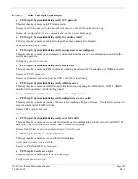
On the PFD:
47.
Repeat the configuration upload as documented above.
48.
Power down PFD1 and MFD1.
A.
AVIONICS Switch (BUS 1 and BUS 2) – Off
B.
MASTER Switch (BAT) – Off
49.
Remove the SD card from the PFD.
50.
Power up MFD1 and PFD1 in Normal mode:
A.
STBY BATT Switch – Arm
B.
Ensure STBY BATT CB is open
C.
AVIONICS Switch (BUS 1 and BUS 2) – On
D.
MASTER Switch (BAT) – On
51.
Verify the BATT S current indication on the bottom corner of the EIS strip reads 0.0 Amps. If the BATT
S current indication does not read 0.0, repeat procedure ensuring all steps have been followed. If the
BATT S current indication still does not read 0.0, return the GEA 71 to Garmin for servicing.
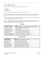
52.
Power down PFD1 and MFD1.
A.
AVIONICS Switch (BUS 1 and BUS 2) – Off
B.
M ASTER Switch (BAT) – Off
53.
Close the STBY BATT CB.
54.
Turn the STBY BATT switch to off.
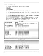
55.
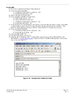
Email the date of calibration, GEA 71 serial number, engine hours, and value of READING #1 and
READING #2 to
avionics@garmin.com
. Please enter “GEA 71 HSCM Calibration Data” in the subject
line, as shown in Figure 2-31.
Figure 2-31. Example Post-Calibration Email
Summary of Contents for G1000 NAV III
Page 1: ...190 00352 00 March 2008 Rev L G1000 NAV III LINE MAINTENANCE MANUAL ...
Page 28: ...Page 1 18 G1000 Nav III Line Maintenance Manual Rev L 190 00352 00 Blank Page ...
Page 120: ...Page 2 92 G1000 Nav III Line Maintenance Manual Rev L 190 00352 00 Blank Page ...
Page 184: ...Page 6 6 G1000 Nav III Line Maintenance Manual Rev L 190 00352 00 Blank Page ...
Page 248: ...Page B 34 G1000 Nav III Line Maintenance Manual Rev L 190 00352 00 Blank Page ...

