G300 Installation Manual – Installation Overview
Page 1-7
190-00921-01
Revision A
1.6.3
Cable Installation
1.
Route the coaxial cable to the unit location. Secure the cable in accordance with good aviation
practice.
2.
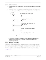
Trim the coaxial cable to the desired length and install the BNC connector (330-00087-00) per
the cabling instructions on Figure 1-2. If the connector is provided by the installer, follow the
connector manufacturer’s instructions for cable preparation.
Figure 1-2. Coaxial Cable Installation
3.
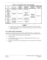
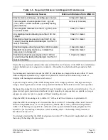
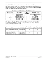
Contacts for the 50, 62, and 78 pin connectors must be crimped onto the individual wires of
the aircraft wiring harness. Table 1-5 list contact part numbers (for reference) and
recommended crimp tools.
1.6.4
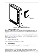
Backshell Assemblies
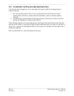
Connector kits include backshell assemblies. The backshell assembly houses the configuration module
and a thermocouple reference junction (if applicable). Garmin’s backshell connectors give the installer
the ability to quickly and easily terminate shield grounds at the backshell housing. The instructions
needed to install the Jackscrew Backshell (190-00313-11), Configuration Module (190-00313-10), and
Thermocouple (190-00313-01) can be downloaded from the Dealer portion of the Garmin website
www.garmin.com
.


