190-01115-01
G3X/G3X Touch Installation Manual
Rev. AC
Page x
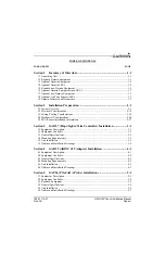
22.3 Antenna Mounting Considerations .............................................................................. 22-4
22.4 Teardrop Footprint Antenna Installation (GA 35, GA 55, and GA 56)....................... 22-9
22.5 ARINC 743 Footprint Antenna Installation (GA 36, GA 37, GA 55A, GA 57X) .... 22-16
22.6 Non-Structural Mount Installation............................................................................. 22-25
22.7 Outline and Installation Drawings ............................................................................. 22-31
Section 23 Engine/Airframe Sensor Installation ...........................................23-1
23.1 Engine/Airframe Sensor Options................................................................................. 23-1
23.2 Engine Sensor Applications......................................................................................... 23-6
23.3 Engine Sensor Installation ......................................................................................... 23-14
Section 24 Connector Installation Instructions .............................................24-1
24.1 Cable Connector Installation ....................................................................................... 24-1
24.2 Thermocouple Installation into a Backshell ................................................................ 24-2
24.3 Jackscrew Configuration Module Installation into a Jackscrew Backshell ................. 24-4
24.4 Jackscrew Backshell Installation Instructions ............................................................. 24-7
25.1 GAD 27 (Flaps/Lights/Trim Controller)...................................................................... 25-1
25.2 GAD 29 (ARINC 429 Adapter)................................................................................... 25-9
25.3 GDU 37X (Display Unit)........................................................................................... 25-13
25.4 GDU 4XX (Display Unit).......................................................................................... 25-18
25.5 GEA 24 (EIS Interface) ............................................................................................. 25-27
25.6 GI 260 (AOA Indicator) ............................................................................................ 25-42
25.7 GMC 305 (AFCS Mode Controller).......................................................................... 25-44
25.8 GMC 307 (AFCS Mode Controller).......................................................................... 25-46
25.9 GMU 11 (Magnetometer) .......................................................................................... 25-48
25.10 GMU 22 (Magnetometer) ........................................................................................ 25-49
25.11 GPS 20A (WAAS GPS Position Source) ................................................................ 25-50
25.12 GSA 28 (Autopilot Servo) ....................................................................................... 25-52
25.13 GSU 25/25B (AHRS/Air Data Sensor Unit) ........................................................... 25-55
25.14 GSU 73 (Sensor Unit).............................................................................................. 25-59
25.15 GTP 59 (Temperature Probe) .................................................................................. 25-71
25.16 GTR 20 (VHF Communications Radio).................................................................. 25-72
25.17 GTX 23 (Mode S Transponder)............................................................................... 25-77
Section 26 G3X w/GSU 25 and/or GAD 29 Interconnect Drawings ............26-1
26.1 Core Interconnect Drawings w/GSU 25 and/or GAD 29 ............................................ 26-1
26.2 External Interconnect Drawings w/GSU 25 .............................................................. 26-10
Section 27 G3X w/GSU 73 Interconnect Drawings .......................................27-1
27.1 Core Interconnect Drawings ........................................................................................ 27-1
27.2 External Interconnect Drawings w/GSU 73 ................................................................ 27-5

