190-01115-01
G3X/G3X Touch Installation Manual - GTR 20 Installation
Rev. AC
Page 21-4
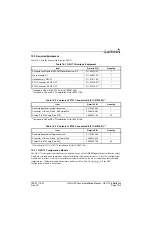
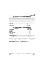
21.4 Installation Considerations
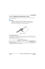
21.4.1 COM Antenna
A COM Antenna that meets TSO-C37( ) and C38( ) or TSO-C169( ), 50W, vertically polarized with
coaxial cable is recommended but not provided.
CAUTION
To avoid damage to the GTR 20, take precautions to avoid transmitting when no
antenna is connected.
21.4.2 Installation Materials
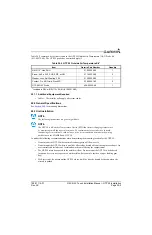
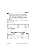
The GTR 20 is intended for use with the standard aviation accessories. The following items are
recommended for installation, but not supplied:
•
Wire (MIL-W-22759/16 or equivalent)
•
Shielded Wire (MIL-C-27500 or equivalent)
•
Mounting Hardware - #10 hardware recommended
•
Push/Pull (that can be manually reset) Circuit Breaker
•
Tie Wraps or Lacing Cord
•
Ring Terminals (for grounding)
•
Coaxial Cable (RG-400, RG-142B or coaxial cable with 50
Ω
impedance meeting applicable
aviation regulations should be used.
21.4.3 Cabling and Wiring
Refer to the interconnect examples in
Use wire and cable meeting the applicable aviation regulation. When routing wire and cable, observe the
following precautions:
•
Keep as short and as direct as possible
•
Avoid sharp bends
•
Avoid routing near power sources (e.g. 400 Hz generators, trim motors, etc.) or near power for
fluorescent lighting
•
Do not route cable near high voltage sources
CAUTION
To avoid damage to the GTR 20, take precautions to prevent Electro-Static Discharge
(ESD) when handling the GTR 20, connectors, and associated wiring. ESD damage can
be prevented by touching an object that is of the same electrical potential as the GTR 20
before handling the GTR 20 itself.
NOTE
The GTR 20 connects to the G3X system using the CAN bus. If communication is lost or no
GDU displays are present, the GTR 20 will automatically tune the emergency frequency
(121.500 MHz) and set the COM radio volume to a pre-determined level. See
for information on configuring the emergency volume level.

