190-01115-01
G3X/G3X Touch Installation Manual - Installation Preparation
Rev. AC
Page 2-2
2.1.1 System Architecture and Interface Capabilities
The functionality of the G3X system is distributed between multiple interconnected devices, some of
which are located in the instrument panel and some of which are remote-mounted elsewhere. An individual
device in the G3X system is often referred to as a “Line Replaceable Unit”, or LRU. This term is used
generically in aviation for devices that can be readily “swapped out” for troubleshooting or repair.
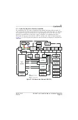
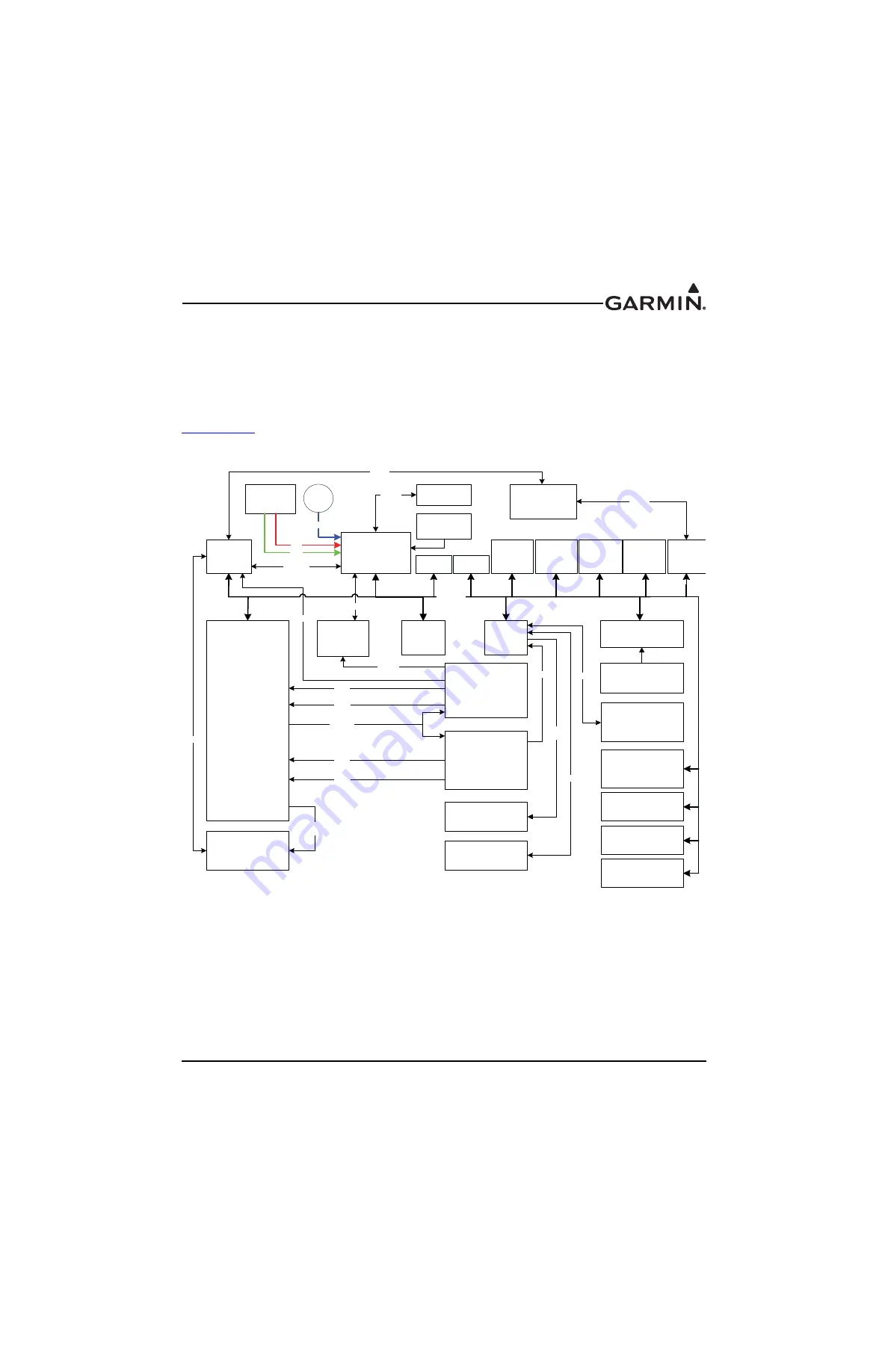
LRUs in the G3X system are interconnected via RS-232 interfaces and a shared CAN bus network (see
). The G3X system can interface to a variety of other devices using RS-232 and ARINC 429
connections.
Figure 2-1 G3X Interconnect Example (GDU 37X)
GDU 370
PFD1
GAD 29
Data
Concentrator
(Optional)
GDU 375
PFD2
(Optional)
GSU 25
ADAHRS 1
GDU 370
MFD
(Optional)
GSA 28
Roll Servo
(Optional)
GMC 305/307
A/P Controller
(Optional)
GEA 24
Engine Analyzer
GTX
Transponder
(Optional)
No. 2 GPS/Com
(Optional*)
No. 1 GPS/Com
(Optional*)
GMA 240
Audio Panel
(Optional)
GARMIN COM OR
NAV/COM
(Optional**)
Third-party
Autopilot
(Optional)
A429
(Autopilot)
A429
(NAV)
A429
(GPS)
RS-232
A429
(NAV)
RS-232
A429
(GPS)
GAP 26
Pitot/AOA
(Optional)
Static
Source
GTP 59
Temp Probe
GMU 22
Magnetometer
RS-232/
RS-485
GSA 28
Pitch Servo
(Optional)
Engine/Airframe
Sensors
Stereo/
Mono
RS-232
Notes:
*Maximum of two (2) COM/NAV
units installed.
**Same as (*) plus GDU to SL40
is TX-only.
AOA
Pitot
RS-232
RS-232
A429
(Air Data)
Static
CAN BUS
RS-232
(Optional)
RS-232
RS-232
(ADS-B)
GDL 39/39R
ADS-B Traffic and
Weather Receiver
(Optional)
GSU 25
ADAHRS 2
(Optional)
RS-232
RS-232
GTR 200 (optional)
GI 260
(Optional)
GAD 27
(Optional)
G5 Standby Flight
Display (Optional)
(Optional)
GSU 25
ADAHRS 3
(Optional)
GSA 28
Yaw Servo
(Optional)
GPS 20A Position
Source (Optional)
GMU 11 Magnetometer
(Optional)

