

190-01115-01
G3X/G3X Touch Installation Manual - Engine/Airframe Sensor Installation
Rev. AC
Page 23-30
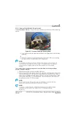
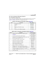
23.3.12 Carburetor Temperature Sensor
UMA 1B10R -
Threaded ¼-28 Platinum Resistance Temperature Detector (RTD) probe. This sensor is
applicable to all carbureted Lycoming and Continental engines.
Rotax 965531 or Rotax 966385 -
This sensor is applicable to all carbureted Rotax engines. Refer to
Rotax Installation Instructions for complete installation details.
23.3.12.1 Lycoming and Continental Engine Sensor Installation
General Installation Guidance:
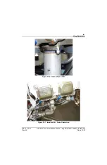
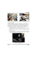
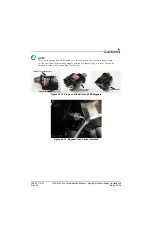
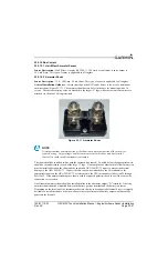
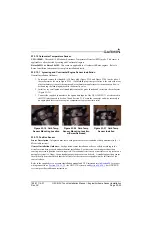
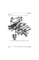
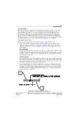
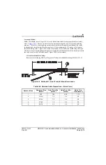
1. Locate and remove the threaded ¼-28 brass plug (Figure 23-19 and Figure 23-20) on the side of
the carburetor as shown in Figure 23-19. If a threaded plug is not present (as is the case with many
older carburetors), consult the engine and/or carburetor manufacturer for instructions on how to
drill and tap the lead plug adjacent to the butterfly valve.
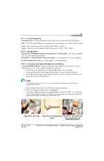
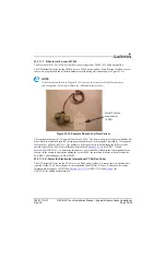
2. Install a very small amount of thread lubricant on the probe threads and insert into the carburetor
3. Connect the supplied connector to the appropriate inputs of the GEA 24/GSU 73 as referenced in
the G3X interconnects in Section 30 and Section 31. Secure the connector and wire assembly to
an appropriate location in the engine compartment to provide strain relief.
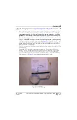
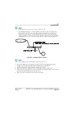
23.3.13 Position Sensor
Sensor Description –
Integrated trim servo with position sensor or standalone slide potentiometer (0 – 5
k
Ω
variable resistor)
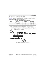
General Installation Guidance –
Each position sensor installation will vary widely according to the
aircraft, motion being sensed, and mechanical installation. For trim servos with integrated position
sensing, no external position sensor is required. If mechanical trim is used or no trim servo is present on a
particular system (i.e. flaps), then a standalone position sensor can be used. A standalone position sensor
should ideally be mounted such that the full travel of the sensor corresponds with the full travel of the
control surface.
Refer to the supplied servo or sensor installation manual and G3X interconnects in
for proper
wiring connections.
systems) provides calibration instructions.
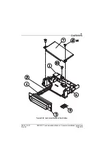
Figure 23-19 Carb Temp
Sensor Mounting Location
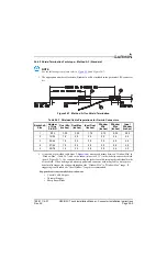
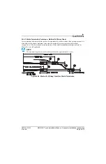
Figure 23-20 Carb Temp
Sensor Mounting Location
w/Screw Removed
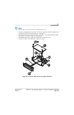
Figure 23-21 Carb Temp
Sensor Installed


