


190-01115-01
G3X/G3X Touch Installation Manual - Connector Installation Instructions
Rev. AC
Page 24-14
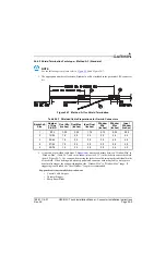
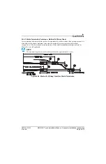
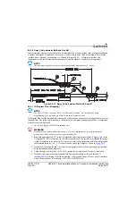
24.4.4 Shield Termination – Method B.1 (Quick Term)
If desired, the drain wire termination (item 3,
) and the floating shield termination (item 5,
) can be effectively combined into a “Quick Term”. This method eliminates the float in the
cable insulation and moves the placement of the window which was described by the dimensions “Window
Min” and “Window Max” from Method A. This technique is depicted in
NOTE
The original purpose for separating the shield drain termination (item 3,
from the float termination (item 5,
) in Method A was to allow for a variety of
lengths for the drain wires so that the shield drain terminations (item 3,
)
would not all “bunch up” in the harness and to eliminate loops in the drain wires. If
Method B is chosen, as described in this section, care must be taken to ensure that all
drain shield terminations can still be inspected. With connectors which require a large
number of shield terminations it may be best to use Method A. This will allow the drain
shield terminations (item 3,
) a larger area to be dispersed across.
Using this method, the instructions from
(Method A) are followed except that:
1. Step 2 is eliminated
2. Steps 3 and 4 are replaced by the following:
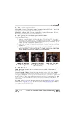
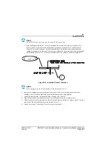
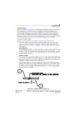
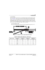
At the end of the shielded cable (item 2,
), strip “Quick Term Min” to “Quick Term
Max” (
) length of the jacket to expose the shield. Next trim the shield so that at most
0.35 inches remains extending beyond the insulating jacket. Fold this remaining shield back over
the jacket.
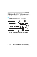
Connect a Flat Braid (item 4,
) to the folded back shield of the prepared cable
assembly. The flat braid should go out the front of the termination towards the connector. It is not
permitted to exit the rear of the termination and loop back towards the connector (
).
Make this connection using an approved shield termination technique.
NOTE
FAA AC 43.13-1B Chapter 11, Section 8 (Wiring Installation Inspection Requirements)
may be a helpful reference for termination techniques.
Preferred Method:
Slide a solder sleeve (item 3,
) onto the prepared cable assembly (item 2,
connect the Flat Braid (item 4,
) to the shield using a heat gun approved for use with solder
sleeves. It may prove beneficial to use a solder sleeve with a pre-installed Flat Braid versus having to
cut a length of Flat Braid to be used. The chosen size of solder sleeve must accommodate both the
number of conductors present in the cable and the Flat Braid (item 4,
NOTE
Reference
for recommended solder sleeves and flat braid. The same
recommendations are applicable to this technique.