

190-01115-01
G3X/G3X Touch Installation Manual - Connector Installation Instructions
Rev. AC
Page 24-15
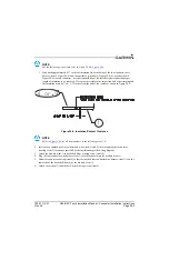
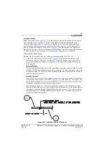
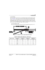
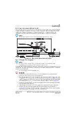
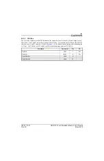
Secondary Method:
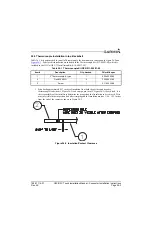
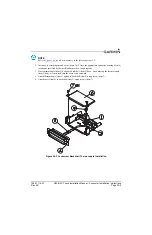
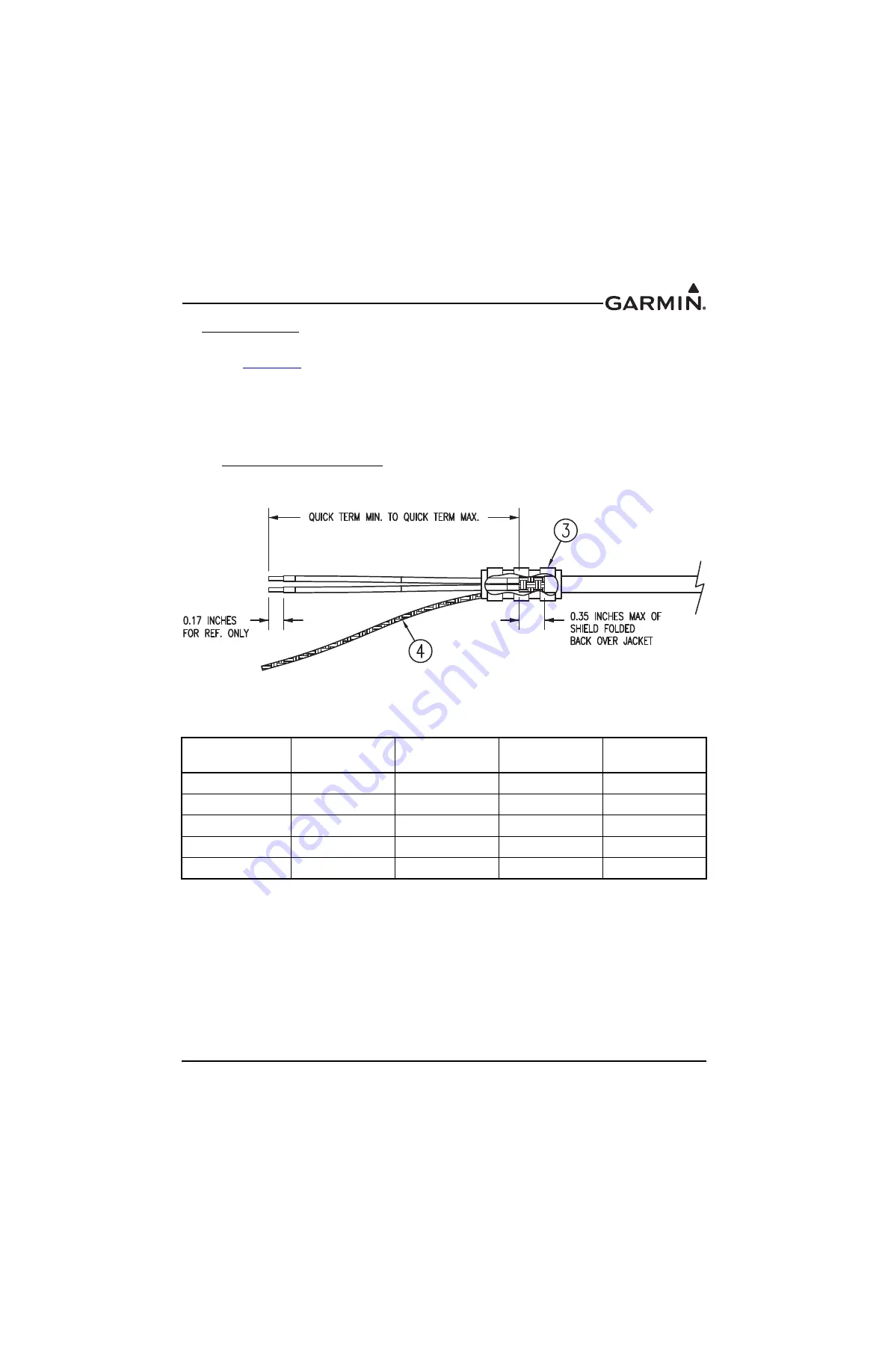
Solder a Flat Braid (item 4, Figure 24-10) to the folded back shield on the prepared cable assembly
(item 2,
). Ensure a solid electrical connection through the use of acceptable soldering
practices. Use care to avoid applying excessive heat that burns through the insulation of the center
conductors and shorts the shield to the signal wire. Slide a minimum of 0.75 inches of Teflon heat
shrinkable tubing (item 3, Figure 24-10) onto the prepared wire assembly and shrink using a heat gun.
The chosen size of heat shrinkage tubing must accommodate both the number of conductors present in
the cable as well as the Flat Braid (item 4, Figure 24-10) to be attached.
Teflon Heat Shrinkable Tubing:
Reference the following MIL-Spec for general Teflon heat shrinkable tubing (M23053/5-X-Y)
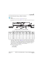
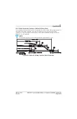
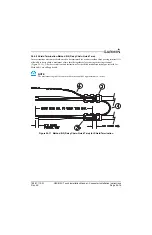
Figure 24-10 Method B.1 (Quick Term) for Shield Termination
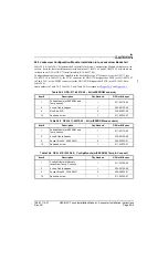
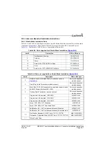
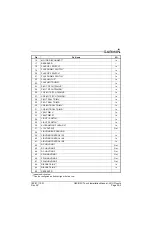
Table 24-8 Shielded Cable Preparations – (Quick Term)
Backshell Size
Number of Pins
Std/HD
Quick Term Min
(inches)
Quick Term Max
(inches)
Quick Term
Float (inches)
1
9/15
1.25
2.25
1.75
2
15/26
1.5
2.5
2.0
3
25/44
1.5
2.5
2.0
4
37/62
1.5
2.5
2.0
5
50/78
1.5
2.5
2.0