190-01115-01
G3X/G3X Touch Installation Manual - LRU Pinouts
Rev. AC
Page 25-66
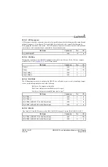
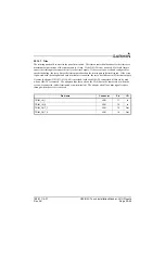
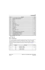
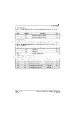
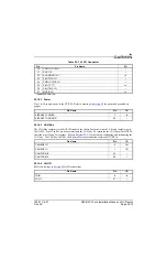
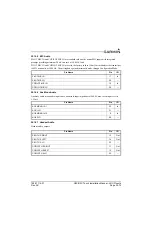
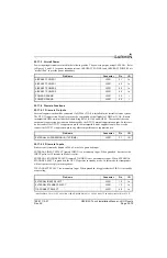
25.14.4.3 RS-485 Input
The GSU 73 contains one channel of RS-485 serial data communications for receiving data from the
GMU 22.
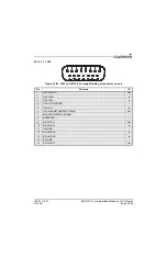
25.14.4.4 CAN Bus
This data bus conforms to the BOSCH standard for Controller Area Network 2.0-B. This bus complies
with ISO 11898. One GDU should be terminated (CAN BUS TERMINATION connected to CAN BUS
LO) and the GSU should be terminated if GSU is located at the end of the bus (see
). See
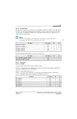
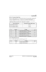
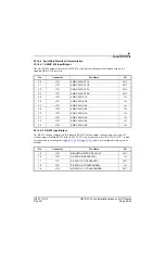
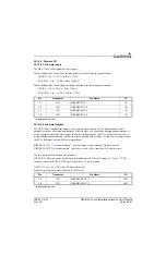
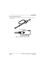
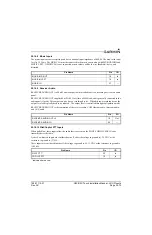
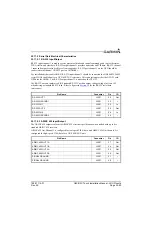
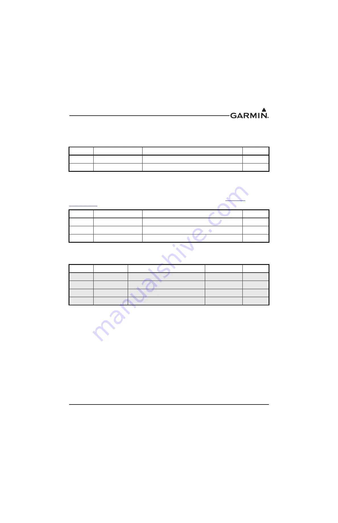
25.14.4.5 Configuration Module Interface
Connect the GSU 73 to the configuration module using the 4 pins listed below.
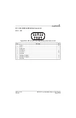
Pin
Connector
Pin Name
I/O
1
J731
MAGNETOMETER RS-485 IN B
IN
2
J731
MAGNETOMETER RS-485 IN A
IN
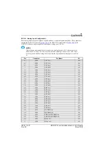
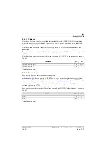
Pin
Connector
Pin Name
I/O
7
J731
CAN BUS HI
I/O
8
J731
CAN BUS LO
I/O
29
J731
CAN BUS TERMINATION
--
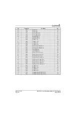
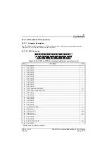
Pin
Connector
Pin Name
Wire Color
I/O
20
J732
CONFIG MODULE CLOCK
WHITE (WHT)
OUT
39
J732
CONFIG MODULE DATA
YELLOW (YEL)
I/O
59
J732
CONFIG MODULE POWER OUT
RED (RED)
OUT
78
J732
CONFIG MODULE GROUND
BLACK (BLK)
--