
190-01115-01 G3X/G3X Touch Installation Manual - GDU 37X Config and Post Install Checkout
Rev. AC
Page 33-129
Current
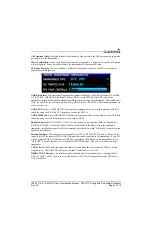
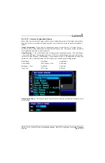
The GEA 24 and GSU 73 have provisions to monitor bus current from two different sources. Current can
be measured either using a shunt resistor such as the UMA 1C4 (50mV/100A type) or a Hall effect sensor
such as the Amploc KEY100 series.
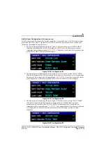
Shunt sensors: Shunt sensors are connected to the SHUNT 1 and SHUNT 2 inputs on the GEA 24 and
GSU 73 (see
). The SHUNT 1 input can be configured to display either
"Bus 1 Amps" or "Main Bus Amps". The SHUNT 2 input can be configured to display either "Bus 2
Amps" or "Essential Bus Amps".
Hall effect sensors: Hall effect current sensors are connected to the GEA 24 or GSU 73 general purpose
(GP) inputs (see
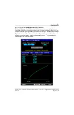
). Hall effect sensors can optionally be calibrated to
adjust for installation differences (see
). The supported configurations for Hall effect
current sensors on GP inputs are similar to those supported for shunt current sensors:
•
Bus 1 Amps (Hall)
•
Bus 2 Amps (Hall)
•
Main Bus Amps (Hall)
•
Essential Bus Amps (Hall)
Vertical Power: When using a Vertical Power unit, configure SHUNT 1 to "Vertical Power Main Bus
Amps" or "Vertical Power Bus 1 Amps" to use primary bus current data from the Vertical Power unit.
Configure Shunt 2 to "Vertical Power Bus 2 Amps" to use secondary bus current data from the Vertical
Power unit.
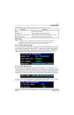
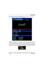
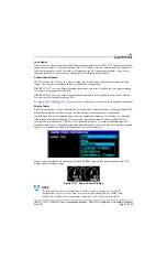
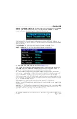
Fuel Flow
The following sensors can be configured for the Fuel Flow input on the GEA 24 or GSU 73:
•
Electronics International FT-60
•
Floscan 201B-6
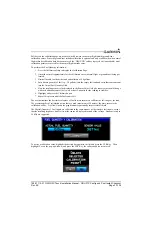
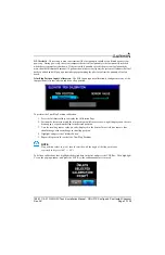
The fuel flow input requires calibration (see
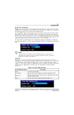
Rotax 912iS/915iS: For the GEA 24, configure the FUEL FLOW input to "Rotax FADEC" to use fuel flow
data from the Rotax 912 FADEC interface.
The GEA 24 and GSU 73 also have provisions for a second fuel flow input (FUEL FLOW 2) to use in
aircraft that require a second fuel flow sensor for differential fuel flow measurement. If both fuel flow
inputs are configured, the displayed fuel flow will be FUEL FLOW 1 (feed) minus FUEL FLOW 2
(return).