
190-01115-01
G3X/G3X Touch Install Manual - GDU 4XX Config and Post Install Checkout
Rev. AC
Page 34-47
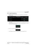
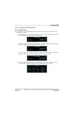
34.4.8.1
On Ground Initial Checkout
NOTE
The following post installation checkout must be followed after every completed
installation. These steps should be followed when using a Garmin mounting kit or non-
Garmin mounting parts to install the GSA 28.
After mounting the GSA 28, please complete the following steps prior to completing the first flight with
the GSA 28.
1. Verify that the flight controls can move from stop to stop without binding or interference. Check
that the GSA 28 output mechanism and added linkage do not come in contact with any part of the
airframe while traveling through its full range of motion.
•
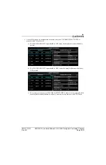
If using a pushrod linkage, verify that the servo crank arm and pushrod cannot experience an
over-center condition when the flight controls are moved through their full range of travel.
Consult
to verify complete servo pushrod installation requirements.
•
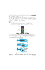
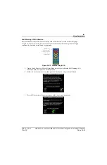
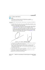
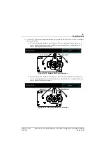
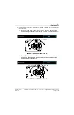
Per Figure 34-14 if using a bridle cable and capstan, verify that the cable is wrapped around
the capstan the required number of turns, the ball is in the center of travel when the flight
controls are in the neutral position, and the ball cannot exit the capstan groove when the
flight controls are moved through their full range of travel. Consult
complete servo capstan installation requirements.
Figure 34-14 360º and 540º Cable Wrap Examples
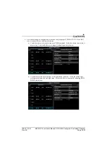
2. Verify that the travel of the flight controls is being limited by the airplane’s primary stops and not
the secondary stops provided by the GSA 28 stop bracket.
3. Ensure the structural integrity of the mounting bracket is adequate for the application and well
secured to the airframe. Bracket deflection caused by normal servo loading and aircraft
acceleration/vibration should be minimal. Also verify there are no cracks or sharp inside corners
that could lead to fatigue failures.
4. Verify the fasteners used to mount the servo to the airframe are installed and have been tightened.
5. Make sure the AP DISC wire is correctly wired and tested.
6. If powering the servo through a “pullable” circuit breaker (recommended), ensure the circuit
breaker is both accessible and easily identifiable to the pilot.
7. Repeat steps 1-7 for all GSA 28 servos in the aircraft.


