190-01115-01
G3X/G3X Touch Installation Manual - Airframe Specific Installation Guidance
Rev. AC
Page A-12
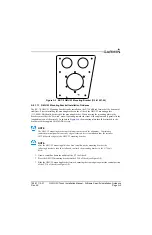
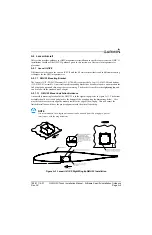
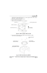
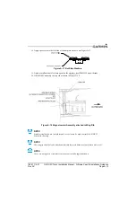
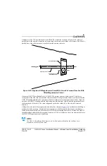
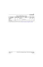
9. Fabricate two disks from 2 BID sheet to the dimensions shown in Figure A-14.
Figure A-14 2 BID Sheet Disk
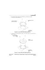
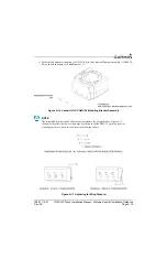
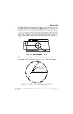
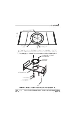
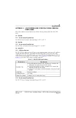
10. Align one
stainless steel
nut plate MS21048-3 (or K1001-3) to each disk using the center hole as a
guide. Match drill 0.098 holes to nut plate and countersink 100° on one side. Refer to
Figure A-15.
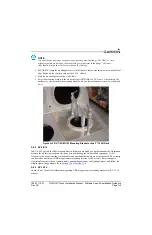
Figure A-15 Aligned Nut Plate And Disk
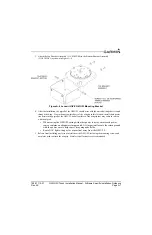
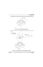
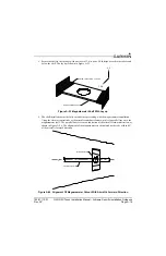
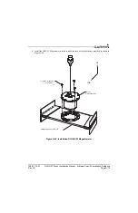
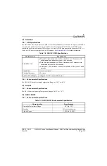
11. Rivet nut plate to disk with MS20426AD3-4 rivets as shown in Figure A-16.
Figure A-16 Riveted Nut Plate And Disk
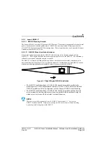
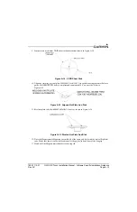
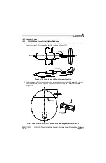
12. Place the Magnetometer Mounting Assembly aft of the spare and level with the typical flight atti-
tude. Make sure there is sufficient head room for the pig tail to bend clear of the wing tip.
13. Match drill the Magnetometer Bracket to the wing rib.