
190-01115-01
G3X/G3X Touch Installation Manual - GDU 470 Installation
Rev. AC
Page 9-3
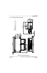
9.3 Installation Information
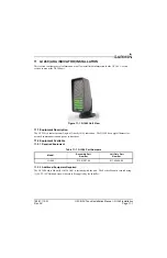
9.3.1 Required Equipment
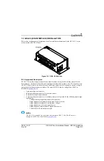
The installation kit (Table 9-1) is required to install the unit. One kit is required for each GDU 470
installed. The installation kits are not included with the GDU 470.
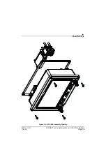
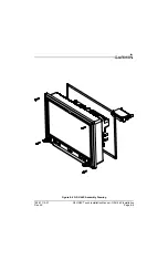
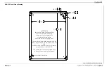
The GDU 470 Nut Plate (
) is included in the installation kit for use when it is not possible to tap
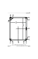
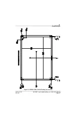
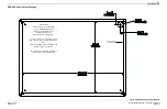
the instrument panel for 6-32 screw threads. A separate drilling guide is included to aid the installation of
a GDU 470 in a panel that formerly contained a GDU 37X display.
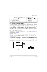
9.3.1.1 GDU 470 PFD Configuration Module
The GDU 470 PFD 1 display uses a configuration module designated as the master system configuration
module. The master system configuration module stores configuration data identical to the PFD
configuration data stored in the PFD memory. The PFD cross-checks the configuration module data
against internal PFD memory and self-configures to match the master system configuration module. The
PFD also maintains control of other LRUs’ configuration and calibration settings except for GSU 73
AHRS calibration settings which are stored in the GSU 73 configuration module (the GSU 25 does not
have a configuration module). This allows critical data to be retained with the airframe even if the PFD 1
display is replaced.
9.3.2 Additional Equipment Required
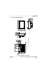
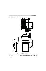
A 3/32” hex drive tool is required to secure the GDU 470 to the panel as described in
Unit
.
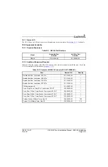
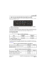
Table 9-1 Contents of GDU 470 Installation Kit (010-12150-02)*
Item
Garmin P/N
Quantity
GDU 4XX Connector Kit*
011-01921-10
1
Nut Plate Kit
115-01725-03
1
GDU 47X Drill Guide
115-01725-04
1
Machine Screw for Panel Mounting, 0.550”, Black
211-00169-01
4
*Contents of the connector kit are listed in Table 9-2
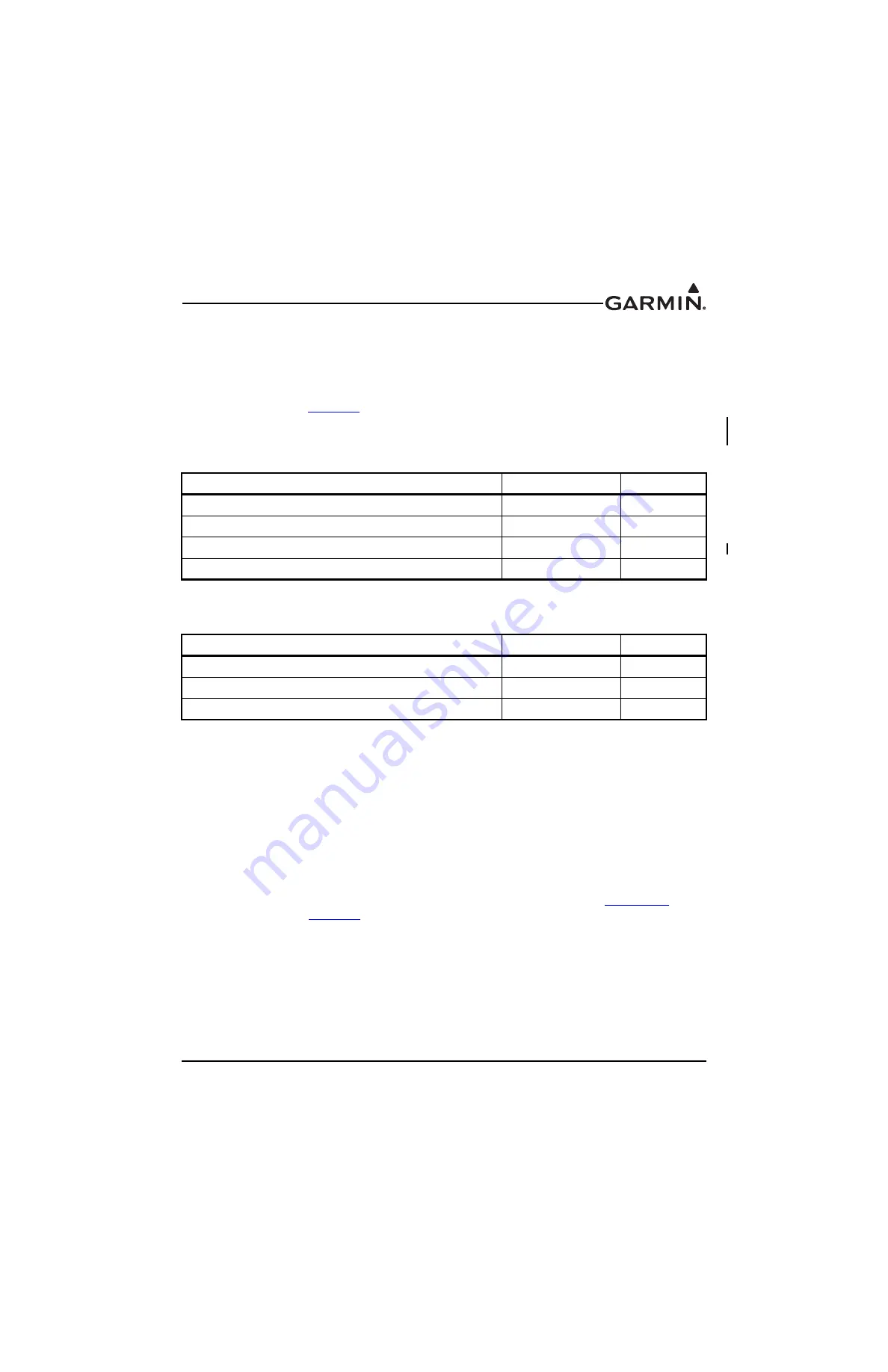
Table 9-2 Contents of GDU 4XX Connector Kit (011-01921-10)
Item
Garmin P/N
Quantity
Sub-Assy, bkshl w/Hdw, Jackscrew
011-01855-04
1
Conn, Rcpt, D-Sub, Crimp Socket
330-00625-50
1
Contact, Sckt, D-Sub, Crimp, Size 20
336-00022-02
30