53
G500/G600 Cockpit Reference Guide
190-00601-03 Rev H
WX GROUP
WX GROUP:
WEA
THER RAD
AR
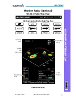
Adjusting the Antenna Bearing
1) Press the small
MFD
knob and turn the large
MFD
knob to move to the
BEARING field.
2) Adjust the azimuth position of the antenna right or left. Monitor the displayed
bearing value in the BEARING field. The range of the bearing is R45° to L45°.
3) Press the
ENT
key to remove the cursor.
When scanning horizontally, a bearing line may be displayed to aid in
positioning the antenna for the vertical scan. If the Bearing Line is not displayed,
perform the following steps:
1) Press the
CONTROL
soft key.
2) Press the
BRG
soft key.
Sector Scan (GWX Radars Only)
1) Press the small
MFD
knob and turn the large
MFD
knob to move to the
SECTOR SCAN field.
2) Turn the small
MFD
knob to select FULL, 60°, 40°, or 20° scan.
3) If desired, readjust the Bearing Line to change the center of the Sector Scan.
Turn the large
MFD
knob to move cursor to the BEARING field and turn the
small
MFD
knob to adjust the line.
Adjusting Gain
WARNING:
Changing the gain in Weather Mode (Garmin GWX units only)
causes precipitation intensity to be displayed as a color not representative
of the true intensity. Remember to return the gain setting to “Calibrated”
for viewing the actual intensity of precipitation.
1) Press the small
MFD
knob and turn the large
MFD
knob to move to the
GAIN field.
2) Turn the small
MFD
knob to adjust the gain for the desirable level. The gain
setting is visible in the gain field as a movable horizontal bar in a flashing
box. The line pointer is a reference depicting the calibrated position.
3) Press the
ENT
key to remove the cursor.
4) To restore the gain to the calibrated position, press the
GAIN CAL
soft key.
Summary of Contents for G500
Page 1: ...G500 G600 Cockpit Reference Guide...
Page 103: ......

