190-01717-B1
G500/G600 TXi Part 23 AML STC Maintenance Manual
Rev. 1
Page 5-17
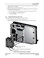
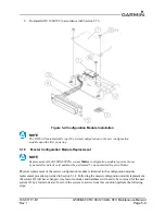
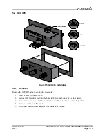
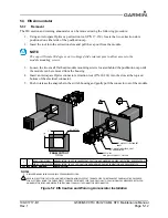
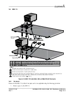
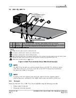
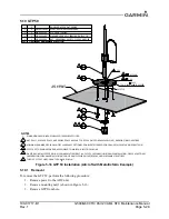
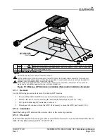
3. Disconnect Pitot-Static lines(GSU75() only).
4. Loosen the two(2) mounting screws on the connector end of the unit.
5. Lift the connector side of the unit and slide the unit towards the connector to remove.
5.5.2
Installation
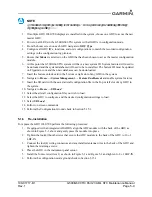
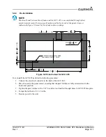
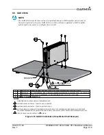
1. Place the unit on the remote rack.
2. Slide the unit back until the feet are fully engaged with the remote rack.
3. Push down and simultaneously turn each retention screw clockwise.
4. Torque each retention screw to 15-20 in-lbs.
5. Connect Pitot-Static Lines (GSU 75() only).
6. Connect electrical connector.
7. Restore unit power.
5.5.3
Checkout
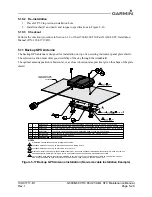
If the mounting bracket bolts have been loosened or bracket mounting(i.e. instrument panel, avionics shelf)
has been moved in any way the following AHRS calibration procedures must be performed as described in
Section 6 of the G500/G600 TXi Part 23 AML STC Installation Manual (P/N: 190-01717-B3):
1. Pitch/Roll Offset Compensation.
2. Magnetometer Calibration.
3. Compass Swing.
4. Heading offset compensation if required by the previous step.
5. Engine Run-up Vibration check.
For the GSU 75() only:
Perform a static and pitot system leak test in accordance with the aircraft manufacturers specification and/
or applicable regulations.
In accordance with 14 CFR Part 43 Appendix E, paragraph (b)(2), Garmin specifies a test procedure
equivalent to Part 43 Appendix E, paragraph (b)(1) with two exceptions. The tests of sub-paragraphs (iv)
(Friction) and (vi) (Barometric Scale Error) are not applicable because the digital outputs of the GSU 75()
are not susceptible to these types of errors.
Perform checkout procedures in Section 5.15.2.

