background image

4-12

Garmin G600 Pilot’s Guide

190-00601-02  Rev. B

For

ewor

d

Sec 1  System

Sec 2


PFD

Sec 3


MFD

Sec 4


Hazar

Avoidance

Sec 5


Additional  Featur

es

Sec 6


Annun.  & Alerts

Sec 7


Symbols

Sec 8


Glossary

Appendix A

Appendix B


Index

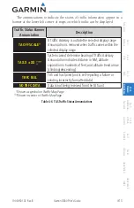
4.2.4 

Traffic System Status


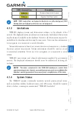
NOTE:

  Refer to the equipment documentation for information on the 

self-test and operating modes. 

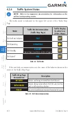
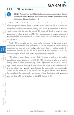
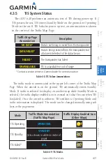
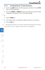
The  traffic  mode  is  indicated  in  the  upper  left  corner  of  the  Traffic  Map 

Page. 

Mode

Traffic Mode Annunciation 

(Traffic Map Page)

Traffic Display 

Enabled Icon 

(Other Maps)

TAS Self-test Initiated

TEST

TAS Operating

OPERATING

TAS Standby

STANDBY

(also shown in white in center of page)

TAS Failed*

FAIL

Table 4-4  TAS Modes

If the unit fails, an annunciation as to the cause of the failure is shown in the 

center of the Traffic Map Page. 

Traffic Map Page 

Annunciation

Description

NO DATA

Data is not being received from the TAS unit

DATA FAILED

Data is being received from the TAS unit, but the 
unit is self-reporting a failure

FAILED

Incorrect data format received from the TAS unit

Table 4-5  TAS Failure Annunciations

Summary of Contents for G600

Page 1: ...G600 Pilot s Guide ...

Page 2: ... transmitted disseminated downloaded or stored in any storage medium for any purpose without the express written permission of Garmin Garmin hereby grants permission to download a single copy of this manual and of any revision to this manual onto a hard drive or other electronic storage medium to be viewed for personal use provided that such electronic or printed copy of this manual or revision mu...

Page 3: ...NTIES EXPRESS OR IMPLIED OR STATUTORY INCLUDING ANY LIABILITY ARISING UNDER ANY WARRANTY OF MERCHANTABILITY OR FITNESS FOR A PARTICULAR PURPOSE STATUTORY OR OTHERWISE THIS WARRANTY GIVES YOU SPECIFIC LEGAL RIGHTS WHICH MAY VARY FROM STATE TO STATE IN NO EVENT SHALL GARMIN BE LIABLE FORANY INCIDENTAL SPECIAL INDIRECT OR CONSEQUENTIAL DAMAGES WHETHER RESULTING FROM THE USE MISUSE OR INABILITY TO USE...

Page 4: ...gree of functional integrity However the pilot must recognize that providing monitoring and or self test capability for all conceivable system failures is not practical Although unlikely it may be possible for erroneous operation to occur without a fault indication shown by the GDU 620 It is thus the responsibility of the pilot to detect such an occurrence by means of cross checking with all redun...

Page 5: ...NING To reduce the risk of unsafe operation carefully review and understand all aspects of the G600 Pilot s Guide Thoroughly practice basic operation prior to actual use During flight operations carefully compare indications from the GDU 620 to all available navigation sources including the information from other NAVAIDs visual sightings charts etc For safety purposes always resolve any discrepanc...

Page 6: ...rating inside nearby hangars can cause an intermittent loss of attitude and heading displays while the aircraft is on the ground Moving the aircraft more than 100 feet away from the source of the interference should alleviate the condition NOTE All visual depictions contained within this document including screen images of the GDU 620 bezel and displays are subject to change and may not reflect th...

Page 7: ...D Sec 3 MFD Sec 4 Hazard Avoidance Sec 5 Additional Features Sec 6 Annun Alerts Sec 7 Symbols Sec 8 Glossary Appendix A Appendix B Index Record of Revisions Part Number Revision Date Page Range Description 190 00601 02 A B 6 10 08 7 8 08 All Production release Update information ...

Page 8: ...uide 190 00601 02 Rev B Foreword Sec 1 System Sec 2 PFD Sec 3 MFD Sec 4 Hazard Avoidance Sec 5 Additional Features Sec 6 Annun Alerts Sec 7 Symbols Sec 8 Glossary Appendix A Appendix B Index This page intentionally left blank ...

Page 9: ...ce 1 6 1 1 10 Attitude Heading Reference System AHRS 1 7 1 1 11 Secure Data Cards 1 8 1 1 12 Pilot Controls 1 8 1 1 12 1 PFD Knob 1 8 1 1 12 2 PFD Bezel Keys 1 9 1 1 12 3 PFD Soft Keys 1 10 1 1 12 4 MFD Knobs 1 11 1 1 12 5 MFD Bezel Keys 1 12 1 1 12 6 MFD Soft Keys 1 12 1 2 System Power Up 1 13 1 3 System Operation 1 14 1 3 1 Using the Page Menus 1 14 1 3 1 1 Navigating a Menu 1 15 1 3 2 Using the...

Page 10: ... 2 7 1 Changing CDI Sources 2 15 2 7 2 Changing CDI Course 2 16 2 7 3 Vertical Deviation Indicator VDI 2 16 2 7 4 Auto Slewing 2 17 2 8 Supplemental Flight Data 2 19 2 8 1 Bearing Pointers 2 19 2 8 2 Temperature Display 2 21 3 Multi Function Display MFD 3 1 3 1 Functional Display Map 3 2 3 2 MFD Soft Key Map 3 3 3 3 Navigation Map Pages 3 4 3 3 1 Default Navigation Page 3 5 3 3 2 Editing Informati...

Page 11: ...3 5 1 2 Active Flight Plan Options 3 58 3 5 2 Waypoint Information Page 3 60 3 5 2 1 Selecting a Waypoint 3 60 3 5 2 2 Waypoint Weather Detail Optional 3 61 3 5 2 3 Waypoint Information Detail 3 62 3 5 2 2 Waypoint Weather Information Optional 3 64 3 5 3 Charts Page Optional 3 65 3 5 3 1 Viewing Charts 3 66 3 5 3 2 Selecting a New Chart by Airport 3 67 3 5 3 3 Selecting a New Chart by FPL NRST or ...

Page 12: ... 4 22 4 4 XM Weather Optional 4 24 4 4 1 Using XM Satellite Weather Products 4 24 4 4 2 Customizing the XM Weather Map 4 24 4 4 3 XM Weather Symbols and Product Age 4 27 4 4 4 Weather Legends 4 29 4 4 5 NEXRAD 4 30 4 4 5 1 Reflectivity 4 31 4 4 5 2 NEXRAD Limitations 4 32 4 4 5 2 NEXRAD Data Viewing Range 4 33 4 4 6 Echo Tops 4 34 4 4 7 Cloud Tops 4 36 4 4 8 XM Lightning 4 38 4 4 9 Cell Movement 4...

Page 13: ...ertainment Radio 5 19 5 5 3 1 Channel Categories 5 20 5 5 3 2 Selecting an XM Radio Channel 5 21 5 5 3 3 XM Radio Volume 5 22 5 5 3 4 XM Radio Channel Presets 5 23 5 5 4 GDL 69 69A Data Link Receiver Troubleshooting 5 24 5 6 Autopilot Operation 5 25 5 6 1 Heading 5 25 5 6 2 Altitude Capture Optional Interface 5 25 5 6 3 Autopilot Navigation 5 26 5 6 3 1 Autopilot Operation with GPSS Enabled Autopi...

Page 14: ... 4 Hazard Avoidance Sec 5 Additional Features Sec 6 Annun Alerts Sec 7 Symbols Sec 8 Glossary Appendix A Appendix B Index Appendix A A 1 SD Card Use and Databases A 1 Jeppesen Databases A 1 Updating the Jeppesen navigation database A 1 Garmin Databases A 2 Updating Garmin databases A 3 Index B 1 ...

Page 15: ... to the pilot through large format displays In normal operating mode the Primary Flight Display PFD presents graphical flight instrumentation attitude heading airspeed altitude vertical speed replacing the traditional flight instrument cluster The Multi Function Display MFD normally displays a full color moving map with navigation information Figure 1 1 G600 System LRU Configuration The system con...

Page 16: ...egrated in the G600 system The G600 Avionics Display System is an advanced technology avionics suite designed to replace the traditional flight instrument cluster The system combinesprimaryflightinstrumentation navigationalinformation andamoving map all displayed on dual 6 5 color screens The G600 system is composed of sub units or Line Replaceable Units LRUs LRUs have a modular design and can be ...

Page 17: ...ather and more The PFD shows primary flight information in place of traditional pitot static and gyroscopic systems and also provides an HSI for navigation The GDU 620 PFD does not have a reversionary mode Figure 1 2 GDU 620 PFD and MFD 1 1 3 GDC 74A The GDC 74A air data computer compiles information from the pitot static system and an outside air temperature OAT sensor The GDC 74A provides pressu...

Page 18: ...nt using an ARINC 429 digital interface to the GDU 620 Figure 1 4 GRS 77 AHRS The IGRF International Geomagnetic Reference Field model is contained in the GRS 77 and is only updated once every five years The IGRF model is part of the Navigation Database At system power up the IGRF models in the GRS 77 and in the Navigation Database are compared and if the IGRF model in the GRS 77 is out of date th...

Page 19: ...e transponder that provides Modes A C and S functions The transponder provides traffic information to the display through an ARINC 429 digital interface NOTE GTX 33 33D can also be used to display traffic information on the GDU 620 GTX 33 33D transponders must be interfaced to a GNS 480 for mode control and squawk code entry 1 1 7 GTP 59 A temperature probe provides Outside Air Temperature OAT dat...

Page 20: ...ition of an XM Satellite Radio audio entertainment receiver Weather data and control of audio channel and volume is displayed on the MFD via a High Speed Data Bus HSDB Ethernet connection The GDL 69A is also interfaced to an audio panel for distribution of the audio signal A subscription to the XM Satellite Radio service is required to enable the GDL 69 69A capability Figure 1 8 GDL 69 69A XM Sate...

Page 21: ...agnetometer unavailable available GPS AHRS Normal Operation AHRS no Mag Mode AHRS no Mag no Air Mode Heading Invalid AHRS no GPS Mode Figure 1 9 AHRS Operation Loss of GPS magnetometer or air data inputs is communicated to the pilot by message advisory alerts refer to Section 6 for specific AHRS alert information Any failure of the internal AHRS inertial sensors results in loss of attitude and hea...

Page 22: ...equired for Terrain Obstacle FliteChart and ChartView database storage as well as Jeppesen aviation and ChartView database updates The Navigation Database update card is generally inserted in the upper SD card for database updates and then removed Other database cards are normally located in the lower SD card NOTE Ensure the GDU 620 is powered off before inserting or removing an SD card NOTE Refer...

Page 23: ...mode for the PFD knob After 15 seconds of inactivity in another mode the PFD knob will revert to Heading mode If the Heading is invalid the PFD knob will revert to Course mode Course CRS Selects Course Select mode Pressing the PFD knob in Course mode will center the needle for a VOR or OBS mode course Altimeter ALT Selects Altitude Select mode Pressing the PFD knob in Altimeter mode will enter the...

Page 24: ...c Setting Select mode Pressing the PFD knob in Baro mode will enter the standard pressure 29 92 in value 1 1 12 3 PFD Soft Keys The soft keys are located along the bottoms of the displays below the soft key labels The soft keys shown depend on the soft key level or page being displayed The soft keys can be used to select the appropriate soft key function Soft Key Labels Soft Keys Figure 1 12 PFD S...

Page 25: ...nd GPS or VOR LOC PFD The PFD soft key displays the BRG1 BRG2 and Back soft keys The BRG2 soft key will only be present if the system is configured for a second GPS or VOR LOC receiver BRG1 The BRG1 soft key cycles through the available bearing 1 indicator modes NAV1 GPS1 ADF or None BRG2 The BRG2 soft key cycles through the available bearing 2 indicator modes NAV2 GPS2 ADF or None This soft key w...

Page 26: ... keys changes range on the Map pages The Up arrow zooms out The Down arrow zooms in The keys also aid in scrolling up and down text pages Menu Displays a context sensitive list of options This list allows the user to access additional features or make setting changes that relate to particular pages Enter ENT Validates or confirms a menu selection or data entry Clear CLR Erases information cancels ...

Page 27: ... 30 seconds after power up Upon power up key annunciator lights also become momentarily illuminated on the GDU 620 display bezels On the PFD the AHRS begins to initialize and displays AHRS ALIGN Keep Wings Level The AHRS should display valid attitude and heading fields typically within the first minute after power up The AHRS can align itself both while taxiing and during level flight When the MFD...

Page 28: ...System Startup Pages Pressing the ENT key or right most soft key acknowledges this information and displays the Navigation Map Page When the interfaced GPS unit has acquired a sufficient number of satellites to determine a position the aircraft s current position is shown on the Navigation Map Page 1 3 System Operation NOTE Refer to Section 6 for detailed descriptions of all alerts and annunciatio...

Page 29: ...the small or large MFD knob to scroll through a list of available options a scroll bar always appears to the right of the window box when the option list is longer than the window box 3 Press the ENT key to select the desired option 4 Press the CLR key or MFD knob to remove the menu and cancel the operation No Options Options for MAP Window Figure 1 15 Page Menu Examples 1 3 2 Using the Soft Key C...

Page 30: ...ettings are managed from the Aux Mode System Setup Page The following settings can be changed Display Brightness Mode and Level Airspeed References Glide Vr Vx and Vy Dual Unit Synchronization CDI and Baro Dual installations only Date Time Date Time Time Format and Time Offset MFD Display Units Distance Speed and Altitude Vertical Speed System Display Units Navigation Angle Reference Pressure Unit...

Page 31: ...ed Quantities Exceptions Display Brightness Level Mode Brightness levels on the PFD and MFD Airspeeds Glide VR VX VY Reference markers on PFD airspeed tape Synchronization CDI On Off BARO On Off Crossfill Nav information to GDU 620 Date Time Date Time Time Format Time Offset Distance and Speed Metric Nautical Crosstrack error HSI Bearing distances information windows Distance information window Fl...

Page 32: ... Index Category Settings Affected Quantities Exceptions Navigation Angle Magnetic North True North Heading Course Bearing Track Desired Track Barometric Setting Inches in Hectopascals hpa Barometric pressure on PFD Temperature Celsius Fahrenheit All temperatures on PFD Table 1 1 Display Units Settings System Setup Page More detail on changing settings is in the Section 3 MFD Aux pages System Setti...

Page 33: ...ghting adjustment can be accomplished using the existing instrument panel dimmer bus or the following procedures Backlighting Adjustment 1 From the first AUX page press the small MFD knob to highlight the Display Brightness Mode box 2 Turn the small MFD knob to select the desired brightness Level and then press ENTER Figure 1 18 Display Brightness Adjustment 3 Turn the large MFD knob to highlight ...

Page 34: ...selects GPS1 on the CDI and GNS1 is in OBS mode any course changes will move the OBS on GNS1 GDU1 and GDU2 if the copilot has GPS1 displayed on the CDI Similarly if the pilot selects GPS2 on the CDI and GNS2 is in OBS mode any course changes will move the OBS on GNS2 GDU1 and GDU2 if the copilot has GPS2 displayed on the CDI AHRS 1 and ADC 1 will only be displayed on GDU 1 AHRS2 and ADC2 will only...

Page 35: ...ord Sec 1 System Sec 2 PFD Sec 3 MFD Sec 4 Hazard Avoidance Sec 5 Additional Features Sec 6 Annun Alerts Sec 7 Symbols Sec 8 Glossary Appendix A Appendix B Index Figure 1 19 Dual Unit Synchronization 2 Turn the small MFD knob to select ON or OFF 3 Press ENT ...

Page 36: ...Guide 190 00601 02 Rev B Foreword Sec 1 System Sec 2 PFD Sec 3 MFD Sec 4 Hazard Avoidance Sec 5 Additional Features Sec 6 Annun Alerts Sec 7 Symbols Sec 8 Glossary Appendix A Appendix B Index This page intentionally left blank ...

Page 37: ...he soft keys below the PFD Figure 2 1 PFD Description Ground Pointer Mode Current Nav Source Current FPL Leg Wpt Distance from Your Present Position to Current FPL Leg Wpt Current Track Desired Track Figure 2 2 PFD Nav Status Bar Description NOTE When navigating to a waypoint very far away the DTK CRS and TRK values displayed on the GDU 620 may differ from those displayed on the navigator however ...

Page 38: ...ng a moving tape The true airspeed is displayed in knots below the Airspeed Indicator The numeric labels and major tick marks on the moving tape are marked at intervals of 10 knots while minor tick marks on the moving tape are indicated at intervals of five knots Speed indication starts at 20 knots The Airspeed Indicator provides Indicated Airspeed True Airspeed and Groundspeed The Airspeed Trend ...

Page 39: ... Operating Range Figure 2 5 Overspeed Indication 2 2 1 Markings A color coded white green yellow and red white barber pole speed range strip is located on the moving tape The colors denote flaps operating range normal operating range caution range and never exceed speed VNE The Airspeed Trend Vector is a vertical pink magenta line extending up or down on the airspeed scale shown to the right of th...

Page 40: ...ystem Sec 2 PFD Sec 3 MFD Sec 4 Hazard Avoidance Sec 5 Additional Features Sec 6 Annun Alerts Sec 7 Symbols Sec 8 Glossary Appendix A Appendix B Index VS1 VFE VS0 VN0 VNE Figure 2 6 Typical Airspeed Tape Markings VYSE VMCA VLE Figure 2 7 Additional Reference Markings ...

Page 41: ...ds are displayed at their respective locations to the right of the airspeed scale The values you set are retained when the unit is repowered Glide Reference Marker Vr Reference Marker Vx Reference Marker Vy Reference Marker Figure 2 8 Reference Speeds 2 3 Attitude Indicator Attitude information is displayed over a virtual blue sky and brown ground with a white horizon line The Attitude Indicator d...

Page 42: ...The Slip Skid Indicator is the bar beneath the roll pointer The indicator moves with the roll pointer and moves laterally away from the pointer to indicate lateral acceleration Slip skid is indicated by the location of the bar relative to the pointer One bar displacement as shown below is equal to one ball displacement on a traditional Slip Skid Indicator Roll Pointer Slip Skid Indicator Roll Scal...

Page 43: ... declutter when the aircraft enters an extreme attitude Only the primary functions will be displayed in these situations The following information is removed from the PFD and corresponding soft keys are disabled when the aircraft is in an unusual attitude PFD Knob Mode Annunciations Ground Speed True Airspeed and Airspeed Units Selected Altitude Barometer Settings and Selected Vertical Speed Verti...

Page 44: ...itude altitude trend altitude bug setting altitude bug and the current BARO setting The Altitude Trend Vector is a vertical magenta line extending up or down on the left side of the Altitude scale The end of the trend vector corresponds to the predicted altitude in 6 seconds if the current vertical speed is maintained The altitude bug is displayed at the selected altitude bug setting A portion of ...

Page 45: ...erter is independent of any autopilot installed in the aircraft The following occur when approaching the Selected Altitude Upon passing through 1000 feet of the Selected Altitude the Selected Altitude shown above the Altimeter changes to black text on a light blue background flashes for 5 seconds Whentheaircraftpasseswithin200feetoftheSelectedAltitude theSelected Altitude changes to light blue tex...

Page 46: ...Indicator Vertical speed data is presented on the bottom left of the PFD A Vertical Speed bug and a bug setting are also available Current Vertical Speed Vertical Speed Bug Vertical Speed Bug Setting Figure 2 19 Vertical Speed V S Tape The Vertical Speed Indicator displays the aircraft vertical speed using a non moving tape The tape can be scaled at 2000 3000 or 4000 fpm as set by the installer Ma...

Page 47: ...ppendix A Appendix B Index VSI set by installer Airspeed Tape Range 2000 fpm 60 kts 3000 fpm 70 kts 4000 fpm 80 kts Table 2 1 Vertical Speed Settings Setting the Vertical Speed Indicator Bug 1 Press the V S key to activate Vertical Speed mode 2 Turn the PFD knob to change the Vertical Speed Bug 3 Press the center of the PFD knob to set the Vertical Speed value to the current vertical speed ...

Page 48: ...current ground track is represented on the HSI by a magenta diamond The HSI also presents turn rate course deviation bearing and navigation source information The MSG annunciation will be shown in the HSI when an unacknowledged message is present on the navigator When the message is acknowledged the MSG annunciation will clear 11 7 6 5 3 2 1 12 10 4 14 15 13 8 9 16 1 Turn Rate Indicator 2 Course P...

Page 49: ...nts in the direction of the set course LOC will automatically be displayed if a localizer frequency is tuned The To From arrow rotates with the course pointer and is displayed when the active NAVAID is received 2 6 1 Setting the Heading Bug The Selected Heading is shown to the upper left of the HSI for 3 seconds after being adjusted The light blue bug on the compass rose corresponds to the Selecte...

Page 50: ...e trend vector stopping at the standard turn rate tick mark corresponding to a predicted heading of 18 from the current heading At rates greater than 4 deg sec an arrowhead appears at the end of the magenta trend vector and the prediction is no longer valid Turn Rate indication Arrowhead shown for a Turn Rate 4 deg sec Standard Turn Rate Standard Turn Rate Current Track Indicator Lubber Line Headi...

Page 51: ...rce magenta for GPS or green for VOR and LOC The full scale limits for the CDI are defined by a GPS derived distance when coupled to GPS When coupled to a VOR or localizer LOC the CDI has the same angular limits as a mechanical CDI If the CDI exceeds the maximum deviation on the scale two dots while coupled to GPS the crosstrack error XTK is displayed below the white aircraft symbol Figure 2 24 Na...

Page 52: ...er an ILS frequency is tuned in the active NAV field A green diamond acts as the VDI Indicator like a glideslope needle on a conventional indicator If a localizer frequency is tuned and there is no glideslope signal NO GS is annunciated The glideslope on an ILS approach is only shown if the current heading is within 90 of the selected course This prevents the glideslope from being displayed during...

Page 53: ...NS navigator and the appropriate frequency is in the active window in the navigator The G600 will Auto Slew the HSI course pointer for an ILS LOC LOC BC LDA or SDF approach when the steps below are completed in the following order 1 The desired approach is selected and activated in the navigator this can be verified by the approach waypoints appearing on the GDU620 MFD Nav Map Page or FPL Page 2 T...

Page 54: ...h Plate 1 The aircraft is flying vectors to final on an active ILS approach with the appropriate approach in the GNS navigator 2 The appropriate ILS frequency must be activate in the navigator 3 Verify that the waypoints for the approach are displayed on the Nav Map Page or the FPL Page of the MFD 4 Upon approaching the final course select NAV on the HSI NOTE If auto CDI switching is active on the...

Page 55: ... on the HSI for NAV and GPS sources The pointers are light blue and are single BRG1 or double lined BRG2 an icon is shown in the respective information window to indicate the pointer type The system must be configured for a second navigation source to show the BRG2 selection When a bearing pointer is displayed its associated information window is also displayed The Bearing Information windows are ...

Page 56: ...f ADF signal validity Bearing 2 Pointer Bearing 1 Pointer Icon Bearing 2 Pointer Icon Bearing 2 Source GPS Level of Service Current Navigation Source CDI Bearing 1 Pointer Bearing 1 Source Figure 2 30 HSI with Bearing Information CDI Source GPS Mode GPS Advisory Suspend MSG LOI OBS SUSP GPS1 GPS2 VOR1 VOR2 LOC1 LOC2 OCN ENR TERM APR LNAV LNAV LPV LNAV VNAV Figure 2 31 PFD HSI Annunciations 1 Press...

Page 57: ...Display The Outside Air Temperature OAT is displayed in the lower left of the PFD The OAT can be displayed in F or C which is configured in the Aux System Setup Page The temperature is derived from the GTP 59 Temperature Probe on the aircraft The displayed temperature is the Static Air Temperature reported by the Air Data Computer This temperature value is corrected for ram air heating effects Fig...

Page 58: ...Guide 190 00601 02 Rev B Foreword Sec 1 System Sec 2 PFD Sec 3 MFD Sec 4 Hazard Avoidance Sec 5 Additional Features Sec 6 Annun Alerts Sec 7 Symbols Sec 8 Glossary Appendix A Appendix B Index This page intentionally left blank ...

Page 59: ...ion Map page 1 are used as the default settings for the optional Weather WX pages The amount of displayed data can be reduced by selecting the DCLTR soft key The Navigation Map can be oriented four different ways North Up NORTH UP Track Up TRACK UP Desired Track Up DTK UP or Heading Up HDG UP Map Orientation Map Scale Range Select Menu Clear Enter Small MFD Knob Select Page Large MFD Knob Select P...

Page 60: ...t corner of the map and represents the top to bottom distance covered by the map To change the map range on any map press the RNG keys on the right side of the bezel 3 1 Functional Display Map Map Group Wx Group opt Aux Group FPL Group Nav Map 1 Nav Map 2 Traffic opt Terrain Wx Data Link Map 1 Wx Data Link Map 2 Wx Data Link Map 3 System Setup XM Info opt XM Radio opt System Status Active FPL Wpt ...

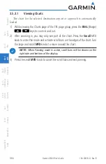
Page 61: ...dance Sec 5 Additional Features Sec 6 Annun Alerts Sec 7 Symbols Sec 8 Glossary Appendix A Appendix B Index 3 2 MFD Soft Key Map The soft keys available depend on the page displayed and the features available The soft key Alerts is present on the far right position in all MFD displays Figure 3 3 MFD Soft Keys ...

Page 62: ...d bearing to pointer location of pointer name andotherpertinent information Map range Wind direction and speed Map orientation Icons for enabled map features Aircraft icon representing present position Nav range ring Flight plan legs Track vector Topography scale Topography data XM NEXRAD Weather XM Lightning XM Storm Cells Symbols used on the MFD are detailed in Section 7 Wind Vector and Speed Ma...

Page 63: ...age Group Turn Large MFD knob Page Turn Small MFD knob Figure 3 5 Page Group and Page Locator 3 3 3 Selecting Page Options 1 Change the fields or the setup of a page by pressing the MENU key and make the necessary adjustments with the MFD knobs 2 Press ENT to accept the displayed value Press the small MFD knob to cancel selection or to end editing 3 3 4 Changing the Navigation Map Range The Range ...

Page 64: ...er feature allows the pilot to progressively step through four levels of decluttering to remove map information The declutter level is displayed in the DCLTR soft key Figure 3 7 Map Declutter Soft Key 1 There are four levels of decluttering DCLTR 0 shows the most detail DCLTR 3 removes the most detail 2 While viewing Navigation Map 1 or 2 press the DCLTR soft key Each successive press of the DCLTR...

Page 65: ...es Tower Land Country Text TRSA Large City ADIZ Medium City Alert Areas Small City Caution Areas Small Town Danger Areas Freeways Warning Areas Highways Large Airports Roads Medium Airports Railroads Prohibited Areas Political Boundaries MOAs User Waypoints Runway Labels Lat Lon Grids Lightning Strike Data VORs NEXRAD Data NDBs Traffic Symbols Intersections Traffic Labels Class B Airspace Water De...

Page 66: ...r present position to the pointer elevation at the pointer and bearing and distance to the pointer from your present position Information is related to the tip of the pointer Elevation at Pointer ETE from present position to tip of pointer Lat Lon at Pointer Map Pointer Present Position Figure 3 8 Navigation Map Pointer Location Information 1 While viewing a Map or Chart page press the small MFD k...

Page 67: ...ads lakes rivers just about everything displayed on the map except route lines When an airport NAVAID or user waypoint is selected on the map display you can review information about the item 1 While viewing the Navigation Map pages of the Map page group press the small MFD knob to activate panning 2 Move the cursor with the small and large MFD knobs to highlight a feature 2 Press ENT to display i...

Page 68: ...s to highlight Measure Bearing Distance and then press ENT Figure 3 10 Navigation Map Measure Distance Function 3 Your present position will be marked as the starting reference point To choose a different starting reference point turn the large or small MFD knobs to desired point and press ENT Figure 3 11 Measure Distance Starting Reference Point 4 Turn the large or small MFD knobs to move the cur...

Page 69: ...ows you to determine the Bearing Distance and Lat Lon position for points selected on the Navigation Map page 3 3 3 Map Setup The Map Setup selection from the Page Menu allows you to customize the displayed items 1 While viewing the Navigation Map 1 or 2 pages of the Map page group press the MENU key to display the Navigation Map Page Menu Figure 3 13 Navigation Map Page Menu 2 With the cursor fla...

Page 70: ...i Viewing Range Off Range North Up At Off Range NEXRD Cell Mov Off Range Rwy Extension Range Off Range Auto Zoom On Off XM Ltng Off Range INT NDB Viewing Range Off Range Land Data On Off VOR Viewing Range Off Range Track Vector Length Off Time Class B TMA Off Range Wind Vector On Off Class C TCA Off Range Nav Range Ring On Off Class D Off Range Topo Data On Off Restricted Off Range Topo Scale On O...

Page 71: ...he Orientation option sets the orientation of the Navigation Map 1 While viewing the Navigation Map 1 or 2 of the Map page group press the MENU key With Map Setup highlighted press ENT With the Map Group active turn the large MFD knob to highlight the Orientation option 2 Turn the small MFD knob to change the highlighted value Figure 3 15 Navigation Map Orientation 3 Press ENT to accept the displa...

Page 72: ...While viewing the Navigation Map 1 or 2 of the Map page group press the MENU key With Map Setup highlighted press ENT With the Map Group active turn the large MFD knob to highlight the North Up At option 2 Turn the small MFD knob to change the highlighted value Figure 3 16 Navigation Map North Up At Orientation Range Selection 3 Press ENT to accept the displayed value The next option will be highl...

Page 73: ...ed once one of the following conditions is met 1 a waypoint is sequenced 2 the aircraft transitions from on ground to in air 3 a point is reached where the Auto Zoom range matches the manual override range known as auto sync 4 Auto Zoom is toggled of and back on in the Navigation Map Setup page Or 5 OBS mode is turned off 1 While viewing the Navigation Map 1 or 2 of the Map page group press the ME...

Page 74: ...es will still be displayed even with Land Data turned off 1 While viewing the Navigation Map 1 or 2 of the Map page group press the MENU key With Map Setup highlighted press ENT With the Map Group active turn the large MFD knob to highlight the Land Data option 2 Turn the small MFD knob to select On or Off Figure 3 18 Navigation Map Land Data 3 Press ENT to accept the displayed value The next opti...

Page 75: ... Vector Aircraft Present Position Figure 3 19 Navigation Map Track Vector 1 While viewing the Navigation Map 1 or 2 of the Map page group press the MENU key With Map Setup highlighted press ENT With the Map Group active turn the large MFD knob to highlight the Track Vector Length option 2 Turn the small MFD knob to select the Track Vector Length time value or Off Figure 3 20 Navigation Map Track V...

Page 76: ...n Figure 3 21 Navigation Map Wind Vector Display 1 While viewing the Navigation Map 1 or 2 of the Map page group press the MENU key With Map Setup highlighted press ENT With the Map Group active turn the large MFD knob to highlight the Wind Vector option 2 Turn the small MFD knob to select the On or Off Figure 3 22 Navigation Map Wind Vector Selection 3 Press ENT to accept the displayed value The ...

Page 77: ...e map range Range Ring Radius Range Ring with Compass Rose Figure 3 23 Navigation Map Range Ring 1 While viewing the Navigation Map 1 or 2 of the Map page group press the MENU key With Map Setup highlighted press ENT With the Map Group active turn the large MFD knob to highlight the Nav Range Ring option 2 Turn the small MFD knob to select On or Off Figure 3 24 Navigation Map Range Ring Selection ...

Page 78: ...ed even with Topo Data turned off Topo data and NEXRAD may not be displayed at the same time Turning on either Topo data or NEXRAD will automatically turn off the other one Turning off either Topo data or NEXRAD will not automatically turn the other one back on Topo Data Off Topo Data On Figure 3 25 Navigation Map Topo Data 1 While viewing the Navigation Map 1 or 2 of the Map page group press the ...

Page 79: ... 6 Annun Alerts Sec 7 Symbols Sec 8 Glossary Appendix A Appendix B Index Figure 3 26 Navigation Map Topo Data Selection 3 Press ENT to accept the displayed value The next option will be highlighted 4 Press the small MFD knob to cancel selection or to end editing and return to the Navigation Map page or turn the large MFD knob to the next option ...

Page 80: ...e will be located on the right side of the display Current Aircraft Altitude Sky Indication Current Ground Level Indication Range of Topography Displayed on the Map Minimum Maximum Range of Topography Displayed on the Map Figure 3 27 Navigation Map Topo Scale 1 While viewing the Navigation Map 1 or 2 of the Map page group press the MENU key With Map Setup highlighted press ENT With the Map Group a...

Page 81: ...ion Terrain Data TheTerrainDataoptionselectswhetherTerrainDataandtheTerrainElevation Scale is shown on the Navigation Map The Terrain Data scale will be located on the right side of the display The Terrain Data Icon will be shown when Terrain has been selected Terrain Data Off Terrain Data On Terrain Data Terrain Data Icon Terrain Elevation Scale Figure 3 29 Navigation Map Terrain Data 1 While vie...

Page 82: ... 6 Annun Alerts Sec 7 Symbols Sec 8 Glossary Appendix A Appendix B Index Figure 3 30 Navigation Map Topo Data Selection 3 Press ENT to accept the displayed value The next option will be highlighted 4 Press the small MFD knob to cancel selection or to end editing and return to the Navigation Map page or turn the large MFD knob to the next option ...

Page 83: ...acle Height is less than 1000 ft AGL Lighted Obstacle Height is less than 1000 ft AGL Unlighted Obstacle Height is greater than 1000 ft AGL Lighted Obstacle Height is greater than 1000 ft AGL Figure 3 31 Navigation Map Obstacle Icons Potential Impact Point Unlighted Obstacle Projected Flight Path 1000 ft 100 ft Threshold Terrain more than 1000 ft below the aircraft altitude Black Terrain between 1...

Page 84: ...press the MENU key With Map Setup highlighted press ENT With the Map Group active turn the large MFD knob to highlight the Obstacle Data option 2 Turn the small MFD knob to select the viewing range or Off Figure 3 34 Navigation Map Obstacle Data Selection 3 Press ENT to accept the displayed value The next option will be highlighted 4 Press the small MFD knob to cancel selection or to end editing a...

Page 85: ...dix B Index Lat Lon Viewing Range The Lat Lon Viewing Range option allows you to select the map range where below that value Lat Lon lines will be shown on the MFD Map ranges above the selected value will not show the Lat Lon lines When Off is selected Lat Lon lines will not be shown Figure 3 35 Navigation Map Lat Lon Selection Lat Lon Reference Information Figure 3 36 Navigation Map Lat Lon Infor...

Page 86: ...o the next option 3 3 3 2 Weather Feature Options Optional The Weather group selection from the Map Setup Page Menu allows you to customizetheNEXRADViewingRange NEXRADCellMovement andLightning Viewing range Weather is an optional feature that requires a GDL 69 69A and an XM Weather subscription 1 While viewing the Navigation Map 1 or 2 page of the Map page group press the MENU key to display the N...

Page 87: ...ducts Topo data and NEXRAD may not be displayed at the same time Turning on either Topo data or NEXRAD will automatically turn off the other one Turning off either Topo data or NEXRAD will not automatically turn the other one back on Figure 3 39 NEXRAD Viewing Range Selection 1 While viewing the Navigation Map Setup page and the Weather Group active turn the large MFD knob to highlight the NEXRAD ...

Page 88: ...ve the selected value will not show NEXRAD Cell Movement When Off is selected NEXRAD Cell Movement will not be shown Figure 3 40 NEXRAD Cell Movement Selection 1 While viewing the Navigation Map Setup page and the Weather Group active turn the large MFD knob to highlight the NEXRAD Cell Movement option 2 Turn the small MFD knob to turn the function on or off 3 Press ENT to accept the displayed val...

Page 89: ...bove the selected value will not show Lightning weather products When Off is selected Lightning weather will not be shown Figure 3 41 Lightning Viewing Range Selection 1 While viewing the Navigation Map Setup page and the Weather Group active turn the large MFD knob to highlight the Lightning Viewing Range option 2 Turn the small MFD knob to change the highlighted value 3 Press ENT to accept the d...

Page 90: ...d a GTX transponder is installed then the GDU 620 will be configured for TAS A pilot can tell which data is being displayed by the label in the top left corner TAS OPERATING vs TIS OPERATING TIS data comes from a GTX transponder Coverage is limited to specific areas as shown in the AIM TAS data comes from a TAS unit such as a Skywatch 497 KTA 810 or other unit Coverage follows the airplane Traffic...

Page 91: ...ghlighted value 3 Press ENT to accept the displayed value 4 Press the small MFD knob to cancel selection or to end editing and return to the Navigation Map page or turn the large MFD knob to the next option 3 3 3 4 Aviation Feature Options The Aviation group selection from the Map Setup Page Menu allows you to customize the display of SafeTaxi information Runway Extensions Intersection NDB locatio...

Page 92: ...e the selected value will not show SafeTaxi When Off is selected SafeTaxi information will not be shown Figure 3 45 Navigation Map Safe Taxi Range Selection 1 While viewing the Navigation Map Setup page and the Aviation Group active turn the large MFD knob to highlight the SafeTaxi Range option 2 Turn the small MFD knob to change the highlighted value 3 Press ENT to accept the displayed value The ...

Page 93: ...ranges above the selected value will not show Runway Extensions When Off is selected Runway Extensions will be shown Figure 3 46 Navigation Map Runway Extension Selection 1 While viewing the Navigation Map Setup page and the Aviation Group active turn the large MFD knob to highlight the Runway Extension option 2 Turn the small MFD knob to change the highlighted value 3 Press ENT to accept the disp...

Page 94: ...bove the selected value will not show Intersection and NDB information When Off is selected the information will not be shown Figure 3 47 Navigation Map INT NDB Viewing Range Selection 1 While viewing the Navigation Map Setup page and the Aviation Group active turn the large MFD knob to highlight the INT NDB option 2 Turn the small MFD knob to change the highlighted value 3 Press ENT to accept the...

Page 95: ...lected value will not show VOR information When Off is selected the information will not be shown Figure 3 48 Navigation Map VOR Viewing Range Selection 1 While viewing the Navigation Map Setup page and the Aviation Group active turn the large MFD knob to highlight the VOR Viewing Range option 2 Turn the small MFD knob to change the highlighted value 3 Press ENT to accept the displayed value The n...

Page 96: ...ve the selected value will not show Class B TMA airspace information When Off is selected the information will not be shown Figure 3 49 Navigation Map Class B TMA Viewing Range Selection 1 While viewing the Navigation Map Setup page and the Aviation Group active turn the large MFD knob to highlight the Class B TMA Viewing Range option 2 Turn the small MFD knob to change the highlighted value 3 Pre...

Page 97: ...ve the selected value will not show Class C TCA airspace information When Off is selected the information will not be shown Figure 3 50 Navigation Map Class C TCA Viewing Range Selection 1 While viewing the Navigation Map Setup page and the Aviation Group active turn the large MFD knob to highlight the Class C TCA Viewing Range option 2 Turn the small MFD knob to change the highlighted value 3 Pre...

Page 98: ...ve the selected value will not show Class D airspace information When Off is selected the information will not be shown Figure 3 51 Navigation Map Class D Viewing Range Selection 1 While viewing the Navigation Map Setup page and the Aviation Group active turn the large MFD knob to highlight the Class D Viewing Range option 2 Turn the small MFD knob to change the highlighted value 3 Press ENT to ac...

Page 99: ...e selected value will not show Restricted airspace information When Off is selected the information will not be shown Figure 3 52 Navigation Map Restricted Airspace Viewing Range Selection 1 While viewing the Navigation Map Setup page and the Aviation Group active turn the large MFD knob to highlight the Restricted Viewing Range option 2 Turn the small MFD knob to change the highlighted value 3 Pr...

Page 100: ...lected value will not show MOA airspace information When Off is selected the information will not be shown Figure 3 53 Navigation Map MOA Military Viewing Range Selection 1 While viewing the Navigation Map Setup page and the Aviation Group active turn the large MFD knob to highlight the MOA Military Viewing Range option 2 Turn the small MFD knob to change the highlighted value 3 Press ENT to accep...

Page 101: ...ve the selected value will not show Other ADIZ airspace information When Off is selected the information will not be shown Figure 3 54 Navigation Map Other ADIZ Viewing Range Selection 1 While viewing the Navigation Map Setup page and the Aviation Group active turn the large MFD knob to highlight the Other ADIZ Viewing Range option 2 Turn the small MFD knob to change the highlighted value 3 Press ...

Page 102: ... be shown on the MFD Map ranges above the selected value will not show TFR information When Off is selected the information will not be shown Figure 3 55 Navigation Map TFR Viewing Range Selection 1 While viewing the Navigation Map Setup page and the Aviation Group active turn the large MFD knob to highlight the TFR option 2 Turn the small MFD knob to change the highlighted value 3 Press ENT to ac...

Page 103: ...elected value will not show Airways When Off is selected airways will not be shown Figure 3 56 Airways Selection 1 While viewing the Navigation Map Setup page and the Aviation Group active turn the large MFD knob to highlight the Airways option 2 Turn the small MFD knob to change the highlighted value 3 Press ENT to accept the displayed value The next option will be highlighted 4 Press the small M...

Page 104: ...tness Mode and Level Airspeeds Glide VR VX and VY Dual Unit Synchronization CDI and Baro Date Time Date Time Time Format and Time Offset MFD Display Units Distance Speed and Altitude Vertical Speed System Display Units Navigation Angle Reference Pressure Units and Temperature Units Figure 3 57 Aux Mode System Setup Page The default values set by the installer during installation are restored by us...

Page 105: ...tic mode will set the display brightness based on the ambient light The manual mode allows the setting of display brightness between 0 and 100 1 Turn the large MFD knob to reach the AUX page group Press the small MFD knob to activate the cursor 2 The Level will be highlighted Turn the small MFD knob to select the Display Brightness Level and then press ENT Figure 3 59 Aux Mode Display Brightness L...

Page 106: ...at the selected speed when the value is set to On Default reference airspeeds are set during installation When power is recycled the values you set will be retained Figure 3 61 Airspeed References shown on PFD when activated 1 While viewing the System Setup page of the AUX page group press the small MFD knob to activate the cursor Turn the large MFD knob to highlight the desired Airspeeds value 2 ...

Page 107: ...re information by Crossfilling or synchronizing information between the two units When Barometric Correction is synchronized any changes to the Barometric Setting on either GDU will change it on both GDUs Crossfill synchronization for CDI and Baro Corrections are selected in Aux mode 1 While viewing the first page of the AUX page group press the small MFD knob and turn the large MFD knob to highli...

Page 108: ...ight Savings Time Offset Atlantic 4 hours 3 hours Eastern 5 hours 4 hours Central 6 hours 5 hours Mountain 7 hours 6 hours Pacific 8 hours 7 hours Alaskan 9 hours 8 hours Hawaiian 10 hours 9 hours Table 3 4 U S Time Zone Offsets 1 While viewing the System Setup page of the AUX page group press the small MFD knob to activate the cursor Turn the large MFD knob to highlight Time Format 2 Turn the sma...

Page 109: ...ce Sec 5 Additional Features Sec 6 Annun Alerts Sec 7 Symbols Sec 8 Glossary Appendix A Appendix B Index Figure 3 64 Date and Time Values 4 A Time Offset may be entered by using the large and small MFD knobs to change the values Press ENT after completing any changes 5 Press the small MFD knob to exit adjustments ...

Page 110: ...units of measurement Figure 3 65 Distance and Speed MFD Display Units 2 Turn the small MFD knob to select Imperial Metric or Nautical and then press ENT The Altitude and Vertical Speed units selection will now be highlighted 3 Turn the small MFD knob to select Feet or Meters and then press ENT Figure 3 66 Altitude and Vertical Speed MFD Display Units 3 4 1 6 System Display Units The System Display...

Page 111: ...the GDU 620 and GNS navigators Figure 3 67 Nav Angle System Display Units 2 Turn the small MFD knob to select Magnetic or True and then press ENT The Barometric Pressure Setting value will now be highlighted Figure 3 68 Barometric Setting System Display Units 3 Turn the small MFD knob to select the Barometric Setting units and then press ENT The Temperature value will now be highlighted Figure 3 6...

Page 112: ...5 Additional Features Sec 6 Annun Alerts Sec 7 Symbols Sec 8 Glossary Appendix A Appendix B Index 3 4 2 XM Information Optional The Aux mode XM Information page displays information about the XM radios service and products when the GDL 69 69A is installed and the XM Radio service is activated Figure 3 70 XM Information ...

Page 113: ...dio programming over long distances without having to constantly search for new stations Based on signal from satellites coverage far exceeds land based transmissions When enabled the XM Satellite Radio audio entertainment is accessible in Aux Mode The information on the XM Satellite Radio display is composed of four areas the Active Channel Available Channels Category of the highlighted Channel a...

Page 114: ...ft Key Database Soft Key Figure 3 72 LRU and Database Information 1 Turn the large MFD knob to the AUX page group 2 Turn the small MFD knob to the System Status page 3 Press the LRU soft key to highlight the first item in the LRU Info window 4 Turn the small MFD knob to scroll through the items in the LRU Info window in case more items are available than are displayed If more items are available t...

Page 115: ...e CDI 3 5 1 Active Flight Plan Page The Active Flight Plan box shows all of the legs of your flight plan with the current leg indicated in magenta Listed are each leg with the Desired Track DTK Distance DIS and Estimated Time of Arrival ETA for the legs METARs are shown for waypoints in the flight plan In the Active Leg Info box in the lower part of the display the Course with beginning and ending...

Page 116: ...he INFO soft key if available to view information about the highlighted waypoint 3 Press the WX soft key if available to view XM weather information about the highlighted waypoint 4 Press the small MFD knob to return to the Active Flight Plan page 3 5 1 2 Active Flight Plan Options The Active Flight Plan page provides information for the flight plan currently in use for navigation To change data f...

Page 117: ...t the desired data item and press ENT 5 Press the small MFD knob to remove the cursor To restore factory default settings for data fields on the Active Flight Plan Page 1 While viewing the Active Flight Plan Page of the FPL page group press MENU to display the Active Flight Plan Page Options window 2 Turn the large MFD knob to highlight Restore Defaults and then press ENT Figure 3 76 Active Flight...

Page 118: ...tion to the selected waypoint as well as its region and Lat Lon coordinates The map window is set up with the same parameters as were selected for Navigation Map Page 1 Facility Type Map Window Map Region Lat Lon Map Scale Map Orientation Bearing Distance to Wpt from Present Position Wpt Info Soft Key Wpt Weather Info Soft Key Facility Identifier Facility Name Facility Location Figure 3 77 Flight ...

Page 119: ...Information Page if the GDL 69 69A is installed and an XM weather subscription is current Pressing the WX soft key will show the weather information page METAR data is displayed first in a decoded fashion then as raw text TAF information is displayed only in its raw form TAF TerminalAerodromeForecast isthestandardformatfor24 hourweather forecasts A TAF typically forecasts significant weather chang...

Page 120: ...by pressing the INFO soft key on the Waypoint Information page The current destination waypoint is the default item shown You may select a different Ident Facility or Location In the Runway window you may view information about the runways available if a highlighted arrow is shown In the Frequency window a scroll bar is shown on the right side of the window when more frequencies are available Airp...

Page 121: ...n but may be changed to find information about other choices Press the small MFD knob to activate the cursor 3 Use the large MFD knob to highlight the field you wish to change and use the small MFD knob to change the value 4 Press the ENT key to save the selected value or press the small MFD knob to cancel editing Runway Information Selection Informationisprovidedforeachrunwayshowingthefollowingde...

Page 122: ... the Frequency window if more frequencies are available Figure 3 82 Waypoint Frequency Information 1 While viewing theWaypoint Information page of the FPL page group press the INFO soft key to view information about the waypoint and then press the small MFD knob to activate the cursor 2 Turn the small MFD knob to scroll through the available frequencies 3 Press the small MFD knob to exit 3 5 2 2 W...

Page 123: ...mation 3 Press the small MFD knob to return to the main Flight Plan page 3 5 3 Charts Page Optional Charts when installed are available in the Flight Plan page group 1 Turn the large MFD knob to the Flight Plan page group 2 Turn the small MFD knob to the Charts page NOTE There are two options for chart services FliteCharts or ChartView FliteCharts displays charts published by the National Aeronaut...

Page 124: ...s automatically loaded 1 While viewing the Charts page of the FPL page group press the RNG Range keys to zoom in and out 2 After zooming in you may only see part of the chart Press the Small MFD knob to enter Pan mode and activate scroll bars on the edges of the chart Turn the large and small MFD knobs to move around the chart NOTE When Panning mode is active scroll bars will be shown on the right...

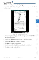
Page 125: ... airport may be chosen by selecting the identifier for the desired airport Figure 3 85 Airport Identifier Selection 1 While viewing the Charts page of the FPL page group press the SELECT soft key to change the airport 2 Use the large MFD knob to move the cursor to highlight a character 3 Use the small MFD knob to change the character 4 Press ENT to accept the selected airport 5 Use the large and s...

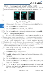
Page 126: ...iewing The Day View offers a better presentation in a bright environment The Night View gives a better presentation for viewing in a dark environment The auto setting allows the user to set a percentage This percentage is the backlight value where the charts page will automatically switch between day and night mode If you set the unit to AUTO 10 then if the backlight is below 10 it will be in nigh...

Page 127: ...Optional GTX 33 330 Transponder required Weather GDL 69 69A XM Satellite Weather 4 1 Terrain During power up of the GDU 620 the terrain obstacle database versions are displayed along with a disclaimer At the same time the Terrain system self test begins A failure message is issued if the terrain test fails Garmin TERRAIN is a non TSO C151b certified terrain awareness system provided as a standard ...

Page 128: ...ain The Terrain page is in the Map page group Terrain is also selectable on the Navigation Map pages 1 Turn the Large MFD knob to the MAP page group 2 Turn the small MFD knob to the Terrain page Map Orientation North Indication Range Rings Altitude Information Terrain Altitude Legend Ownship Symbol at Present Position 360 Range Ring Selection 120 Arc Selection Page Name Figure 4 1 Terrain Page wit...

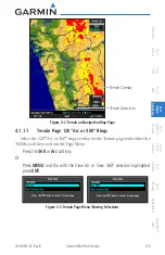
Page 129: ...ix B Index Terrain Data Icon Terrain Overlay Figure 4 2 Terrain on Navigation Map Page 4 1 1 1 Terrain Page 120 Arc or 360 Rings Select the 120 Arc or 360 rings overlay for the Terrain page with either the 360 Arc soft keys or from the Page Menu Press the 360 or Arc soft key Or Press MENU and the with the View Arc or View 360 selection highlighted press ENT Figure 4 3 Terrain Page Menu Viewing Sel...

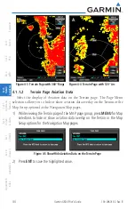
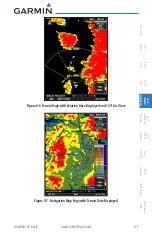
Page 130: ...n Page Aviation Data Select the display of Aviation data on the Terrain page The Page Menu selections allow you to hide or show aviation data overlay on the Terrain or the Map Setup options for the Navigation Map pages 1 While viewing the Terrain page of the MAP page group press MENU for Map selections to hide or show aviation data overlay on the Terrain or the Map Setup options for the Navigation...

Page 131: ...Sec 2 PFD Sec 3 MFD Sec 4 Hazard Avoidance Sec 5 Additional Features Sec 6 Annun Alerts Sec 7 Symbols Sec 8 Glossary Appendix A Appendix B Index Figure 4 6 Terrain Page with Aviation Data Displayed and 120 Arc View Figure 4 7 Navigation Map Page with Terrain Data Displayed ...

Page 132: ...e alerts TERRAIN utilizes terrain and obstacle databases that are referenced to mean sea level MSL Using the GPS position and GPS MSL altitude TERRAIN displays a 2 D picture of the surrounding terrain and obstacles relative to the position and altitude of the aircraft Furthermore the GPS position and GPS MSL altitude are used to calculate and predict the aircraft s flight path in relation to the s...

Page 133: ...abase and data may be inaccurate Never use this information for navigation or to maneuver to avoid obstacles Terrain information is based on terrain elevation information in a database that may contain inaccuracies Terrain information should be used as an aid to situational awareness Never use it for navigation or to maneuver to avoid terrain TERRAIN uses terrain and obstacle information supplied ...

Page 134: ...ce TIS is configured a STANDBY OPERATE and TNA MUTE soft key will be displayed If a Traffic Advisory System TAS is configured a STANDBY OPERATE TEST and ALT MODE soft key will be displayed 4 2 1 Displaying and Operating Traffic TAS Systems The unit must be in operating mode for traffic to be displayed The ability to switch from standby to operating mode on the ground is especially useful for scann...

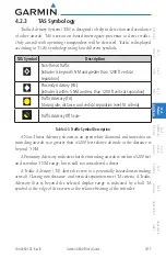
Page 135: ...fic Advisory Off Scale Aircraft is Out of Range 1200 ft Above and Climbing Operating Mode Traffic Advisory Aircraft is 1200 ft Above and Climbing Range Ring Diameter Non Threat Traffic Proximity Advisory 1200 ft Above and Climbing Non Bearing Traffic System is Unable to Determine Bearing Aircraft Distance is 8 0 NM 1100 ft Above and Descending Ownship Symbol Figure 4 8 Traffic Map Page TAS 4 2 1 2...

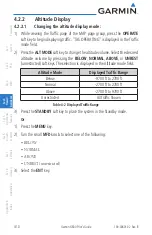
Page 136: ...e Traffic mode field 2 Press the ALT MODE soft key to change the altitude volume Select the desired altitude volume by pressing the BELOW NORMAL ABOVE or UNREST unrestricted soft keys The selection is displayed in the Altitude mode field Altitude Mode Displayed Traffic Range Below 9700 ft to 2700 ft Normal 2700 ft to 2700 ft Above 2700 ft to 9700 ft Unrestricted All Traffic Shown Table 4 2 Display...

Page 137: ...imity Advisory PA intruder is within 5 NM and less than 1200 ft vertical separation Traffic Advisory TA closing rate distance and vertical separation meet TA criteria Traffic Advisory Off Scale Table 4 3 Traffic Symbol Description A Non Threat Advisory shown as an open white diamond indicates that an intruding aircraft is at greater than 1200 feet relative altitude or the distance is beyond 5 NM A...

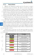
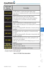
Page 138: ...e Traffic Mode Annunciation Traffic Map Page Traffic Display Enabled Icon Other Maps TAS Self test Initiated TEST TAS Operating OPERATING TAS Standby STANDBY also shown in white in center of page TAS Failed FAIL Table 4 4 TAS Modes If the unit fails an annunciation as to the cause of the failure is shown in the center of the Traffic Map Page Traffic Map Page Annunciation Description NO DATA Data i...

Page 139: ...tion TA OFF SCALE A Traffic Advisory is outside the selected display range Annunciation is removed when traffic comes within the selected display range TA X X XX System cannot determine bearing of Traffic Advisory Annunciation indicates distance in NM altitude separation in hundreds of feet and altitude trend arrow climbing descending TRFC FAIL TAS unit has failed unit is self reporting a failure ...

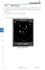
Page 140: ...rts Sec 7 Symbols Sec 8 Glossary Appendix A Appendix B Index 4 2 5 Traffic Pop Up When the GDU 620 MFD is displaying any page other than the NAV Traffic page and a traffic threat is imminent the Traffic Warning page will be displayed Press ENT to go directly to the Traffic page Or Press CLR to return to the previously viewed page Figure 4 9 Traffic Pop Up ...

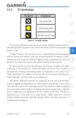
Page 141: ... traffic page soft keys Traffic Information Service TIS is designed to help in detection and avoidance of other aircraft TIS uses the Mode S transponder for the traffic data link TIS receives traffic information from ground stations and is updated every five seconds The GDU 620 displays up to eight traffic targets within a 7 5 NM radius from 3000 feet below to 3500 feet above the requesting aircra...

Page 142: ...the large MFD knob to select the Map Page Group 2 Turn the small MFD knob to select the Traffic Map Page 3 Confirm TIS is in Operating Mode Select the OPERATE soft key to begin displaying traffic Or 1 Press the MENU Key 2 Select Operate Mode shown ifTIS is in Standby Mode and then press the ENT key Traffic Advisory Aircraft is 800 feet above climbing and moving away Operating Mode Traffic Advisory...

Page 143: ... the screen at the relative bearing of the intruder TIS also provides a vector line showing the direction in which the traffic is moving to the nearest 45 Traffic information for which TIS is unable to determine the bearing non bearing traffic is displayed in the center of the Traffic Map Page or in a banner at the lower left corner of maps other than the Traffic Map Page on which traffic can be d...

Page 144: ...nor authorized as a direct result of a TIS intruder display or TIS advisory While TIS is a useful aid to visual traffic avoidance it has some system limitations that must be fully understood to ensure proper use Many of these limitations are inherent in secondary radar surveillance In other words the information provided by TIS will be no better than that provided to ATC TIS will only display airc...

Page 145: ...d station uses a predictive algorithm in its tracking software This algorithm uses track history data to extrapolate intruders to their expected positions consistent with the time of display in the cockpit Occasionally aircraft maneuvering will cause this algorithm to induce errors in the display These errors primarily affect relative bearing information and traffic target track vector it will lag...

Page 146: ...erated As long as a single TA remains on the display no additional voice alerts are generated If a second TA appears on the display or if the number of TAs initially decreases and then subsequently increases another voice alert is generated A Traffic Not Available TNA voice alert is generated when the TIS service becomes unavailable or is out of range TIS may be unavailable in the radar coverage a...

Page 147: ...ta stream FAILED The transponder has failed UNAVAILABLE TIS is unavailable or out of range Contact a service center or Garmin dealer for corrective action Table 4 8 TIS Failure Annunciations The traffic mode is annunciated in the upper left corner of the Traffic Map Page When the aircraft is on the ground TIS automatically enters Standby Mode If traffic is selected for display on another map while...

Page 148: ...D knob to the MAP page group and then turn the small MFD knob to the Traffic Map Page 2 Select the STANDBY or OPERATE soft key to switch between modes The mode is displayed in the upper left corner of the Traffic Map Page Or 1 Press the MENU key 2 Select Operate mode or Standby mode whether airborne or on the ground 3 Press the ENT key The annunciations indicate the status of traffic information a...

Page 149: ...rs if traffic data is not refreshed within 6 seconds If after another 6 seconds data is not received traffic is removed from the display The quality of displayed traffic information is reduced as the age increases TRFC COAST The displayed data is not current 6 to 12 seconds since last message The quality of displayed traffic information is reduced when this message is displayed TRFC RMVD Traffic i...

Page 150: ...ined in the Refresh Rate column If for any reason a weather product is not refreshed within the 30 60 or 90 minute Expiration Time intervals the data is considered expired and is removed from the display This ensures that the displayed data is consistent with what is currently being broadcast by XM Satellite Radio services If more than half of the expiration time has elapsed from the time the data...

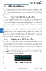
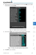
Page 151: ...Symbols Sec 8 Glossary Appendix A Appendix B Index 2 With the Data Link Setup Menu displayed turn the Large MFD knob to select the desired item and press ENT Figure 4 12 Weather Data Link Setup Menu Options 3 Turn the small MFD knob to select the desired weather feature option Figure 4 13 Weather Data Link Setup Menu Option Selection 4 Press ENT to save a selection ...

Page 152: ...ap Page WX Page Menu Weather Setup Menu Item Adjustment NEXRAD Data Off 50 NM to 2000 NM Echo Top Data Off 50 NM to 2000 NM Cloud Top Data Off 50 NM to 2000 NM Ltng Data Off 50 NM to 2000 NM Cell Mov Data Off 50 NM to 2000 NM SIG Air Off 50 NM to 2000 NM METAR Data Off 50 NM to 2000 NM SFC Data Off 50 NM to 2000 NM SFC Time Current 12 Hr 24 Hr 36 Hr and 48 Hr Frz Lvl Data Off 50 NM to 2000 NM Wnd ...

Page 153: ...represent the rate at which weather data is updated or new content is received by the Data Link Receiver Weather data is refreshed at intervals that are defined and controlled by XM Satellite Radio and its data vendors Symbol Weather Product Expiration Time Minutes Refresh Rate Minutes NEXRAD NEXRAD and Echo Top Mutually Exclusive 30 5 Echo Top Cloud Top and Echo Top Mutually Exclusive NEXRAD and ...

Page 154: ...ec 5 Additional Features Sec 6 Annun Alerts Sec 7 Symbols Sec 8 Glossary Appendix A Appendix B Index Symbol Weather Product Expiration Time Minutes Refresh Rate Minutes Flood Severe Thunderstorm Tornado Sunny Part Sun Cloudy Rainy T Storm Snow Windy Foggy Haze High Low Temp Table 4 12 Weather Symbols and Aging Times ...

Page 155: ...bols Sec 8 Glossary Appendix A Appendix B Index 4 4 4 Weather Legends The Legend soft key displays a pop up legend of the currently used weather products Pressing the LEGEND soft key again the MFD knob the ENT or CLR keys will remove the legend 1 A mini legend is always displayed on a WX Data Link Map page for the applicable weather products Figure 4 14 Weather Legends ...

Page 156: ...gical information for the continental United States and selected overseas locations The maximum range of a single NEXRAD radar site is 250 NM The NEXRAD network provides important information about severe weather for air traffic safety NEXRADdataisnotreal time Thelapsedtimebetweencollection processing and dissemination of NEXRAD images can be significant and may not reflect the current radar synop...

Page 157: ...e or is off line 4 4 5 1 Reflectivity Reflectivity is the amount of transmitted power returned to the radar receiver Colors on the NEXRAD display directly correlate to the level of detected reflectivity Reflectivity as it relates to hazardous weather can be very complex The role of radar is essentially to detect moisture in the atmosphere Simply put certain types of weather reflect radar better th...

Page 158: ...mpled at the minimum antenna elevation angle An individual NEXRAD site cannot depict high altitude storms at close ranges It has no information about storms directly over the site When zoomed in to a range of 30 NM each square block on the display represents an area of four square kilometers The intensity level reflected by each square represents the highest level of NEXRAD data sampled within the...

Page 159: ...age 1 2 or 3 When Off is selected NEXRAD weather will not be shown Figure 4 17 NEXRAD Viewing Range Selection 1 While viewing a WX Data Link Map page of the WX page group press the MENU key to display the Page Menu Options The cursor flashes on the Weather Setup option Press ENT 2 The NEXRAD Data Viewing Range value will be highlighted Turn the small MFD knob to highlight the desired value 3 Press...

Page 160: ...on elevation and direction of the highest radar echo The highest radar echo does not indicate the top of a storm or clouds rather it indicates the highest altitude at which precipitation is detected Information is derived from NEXRAD data Figure 4 18 XM Weather Echo Tops The display of radar coverage is always active when either NEXRAD or ECHO TOPS is selected Areas where NEXRAD radar coverage and...

Page 161: ... or 3 When Off is selected Echo Tops will not be shown Figure 4 19 Echo Top Viewing Range Selection 1 While viewing a WX Data Link Map page of the WX page group press the MENU key to display the Page Menu Options The cursor flashes on the Weather Setup option Press ENT 2 Turn the large MFD knob to highlight the Echo Top Data Viewing Range value 3 Turn the small MFD knob to highlight the desired va...

Page 162: ...play of Cloud Tops is mutually exclusive with Echo Tops and NEXRAD Cloud Tops data depicts cloud top altitudes as determined from satellite imagery Figure 4 20 XM Weather Cloud Tops To display the Cloud Tops legend select the LEGEND soft key when Cloud Tops is selected for display Since Cloud Tops and Echo Tops use the same color scaling to represent altitude display of these weather products is m...

Page 163: ... or 3 When Off is selected Cloud Tops will not be shown Figure 4 21 Cloud Top Viewing Range Selection 1 While viewing a WX Data Link Map page of the WX page group press the MENU key to display the Page Menu Options The cursor flashes on the Weather Setup option Press ENT 2 Turn the large MFD knob to highlight the Cloud Top Data Viewing Range value 3 Turn the small MFD knob to highlight the desired...

Page 164: ...ghtning strikes A strike icon represents a strike that has occurred within a two kilometer region The exact location of the lightning strike is not displayed Figure 4 22 XM Weather Lightning Lightning Data Viewing Range The Lightning Data Viewing Range option allows you to select the map range where below that value Lightning weather products will be shown on the selected MFD Wx Data Link Map page...

Page 165: ...knob to highlight the desired value Press ENT to accept the displayed value The next option will be highlighted 4 Press the small MFD knob to cancel selection or to end editing and return to the Navigation Map page or turn the large MFD knob to the next option 4 4 9 Cell Movement Cell Movement data shows the location and movement of storm cells as identified by a ground based system Cells are repr...

Page 166: ...3 When Off is selected Cell Movement will not be shown Figure 4 25 Cell Movement Viewing Range Selection 1 While viewing a WX Data Link Map page of the WX page group press the MENU key to display the Page Menu Options The cursor flashes on the Weather Setup option Press ENT 2 Turn the large MFD knob to highlight the Cell Movement Data Viewing Range value 3 Turn the small MFD knob to highlight the ...

Page 167: ...is issued for hazardous convective weather A localized SIGMET is a significant weather condition occurring at a localized geographical position When enabled SIGMET AIRMETs advise the pilot of potentially hazardous weather other than convective activity to all aircraft The advisory covers an area of at least 3 000 square miles at any one time SIGMET AIRMET data covers icing turbulence dust and volc...

Page 168: ... 3 When Off is selected SIGMET AIRMET will not be shown Figure 4 27 SIGMET AIRMET Viewing Range Selection 1 While viewing a WX Data Link Map page of the WX page group press the MENU key to display the Page Menu Options The cursor flashes on the Weather Setup option Press ENT 2 Turn the large MFD knob to highlight the SIG AIR Viewing Range value 3 Turn the small MFD knob to highlight the desired va...

Page 169: ...E METAR information is only displayed within the installed aviation database service area METAR METeorological Aerodrome Report known as an Aviation Routine Weather Report is the standard format for current weather observations METARs are updated hourly and are considered current METARs typically contain information about the temperature dew point wind precipitation cloud cover cloud heights visib...

Page 170: ... When Off is selected METARs will not be shown Figure 4 29 METAR Viewing Range Selection 1 While viewing a WX Data Link Map page of the WX page group press the MENU key to display the Page Menu Options The cursor flashes on the Weather Setup option Press ENT 2 Turn the large MFD knob to highlight the METAR Data Viewing Range value 3 Turn the small MFD knob to highlight the desired value Press ENT ...

Page 171: ... hours by pressing the SRFC TIME soft key or in the Page Menu Weather Setup options When enabled the Surface Analysis forecast shows frontal lines indicat ing weather fronts and the direction they are moving High and Low pressure centers are noted with a large H or L The Forecast Time menu item will step through the intervals manually Figure 4 30 XM Weather Surface Analysis and City Forecast A Col...

Page 172: ...merged with a warm front The line alternates with the blue triangle and orange half moon symbols on the same side of the line pointing in the direction the front is moving Figure 4 34 XM Weather Occluded Front Surface Data Viewing Range The Surface Data Viewing Range option allows you to select the map range where below that value Surface Data weather products will be shown on the selected MFD Wx ...

Page 173: ...ecast time when the Surface and City Forecast weather products will appear on the selected MFD Wx Data Link Map page 1 2 or 3 Forecasts are available for intervals of current 12 24 36 and 48 hours You may also select an interval by pressing the SRFC TIME soft key on the Wx Data Link Map page Figure 4 36 Surface Data Time Selection 1 While viewing a WX Data Link Map page of the WX page group press ...

Page 174: ...ndix A Appendix B Index 4 4 13 Freezing Level Freezing Level data shows the color coded contour lines for the altitude and location at which the Freezing Level is found When no data is displayed for a given altitude the data for that altitude has not been received or is out of date and has been removed from the display New data appears at the next update Figure 4 37 XM Weather Freezing Levels ...

Page 175: ...or 3 When Off is selected Freezing Level Data will not be shown Figure 4 38 Freezing Level Viewing Range Selection 1 While viewing a WX Data Link Map page of the WX page group press the MENU key to display the Page Menu Options The cursor flashes on the Weather Setup option Press ENT 2 Turn the large MFD knob to highlight the Frz Lvl Viewing Range value 3 Turn the small MFD knob to highlight the d...

Page 176: ...dix A Appendix B Index 4 4 14 Winds Aloft Winds Aloft data shows the forecast wind speed and direction at the surface and at selected altitudes Altitudes can be selected in 3000 foot increments from the surface up to 42 000 feet MSL Pressing the WIND DOWN or WIND UP soft keys steps down or up in 3 000 foot increments Figure 4 39 XM Weather Winds Aloft Figure 4 40 XM Weather Winds Aloft Legend ...

Page 177: ... 3 When Off is selected Winds Aloft will not be shown Figure 4 41 Winds Aloft Data Viewing Range Selection 1 While viewing a WX Data Link Map page of the WX page group press the MENU key to display the Page Menu Options The cursor flashes on the Weather Setup option Press ENT 2 Turn the large MFD knob to highlight the Winds Aloft Data Viewing Range value 3 Turn the small MFD knob to highlight the ...

Page 178: ...rface up to 42 000 feet MSL Pressing the WIND DOWN or WIND UP soft keys steps down or up in the 3 000 foot increments Figure 4 42 Winds Aloft Altitude Selection 1 While viewing a WX Data Link Map page of the WX page group press the MENU key to display the Page Menu Options The cursor flashes on the Weather Setup option Press ENT 2 Turn the large MFD knob to highlight the Winds Aloft Altitude value...

Page 179: ...un Alerts Sec 7 Symbols Sec 8 Glossary Appendix A Appendix B Index 4 4 15 County Warnings County data provides specific public awareness and protection weather warningsfromtheNationalWeatherService NWS Thiscanincludeinformation on fires tornadoes severe thunderstorms flood conditions and other natural disasters Figure 4 43 XM Weather County Warnings ...

Page 180: ...ected County Data will not be shown Figure 4 44 County Data Viewing Range Selection 1 While viewing a WX Data Link Map page of the WX page group press the MENU key to display the Page Menu Options The cursor flashes on the Weather Setup option Press ENT 2 Turn the large MFD knob to highlight the County Data Viewing Range value 3 Turn the small MFD knob to highlight the desired value Press ENT to a...

Page 181: ...red in Section 4 4 Traffic covered in Sections 4 2 and 4 3 SafeTaxi diagrams provide detailed taxiway runway and ramp information at more than 700 airports in the United States By decreasing range on an airport that has a SafeTaxi diagram available a close up view of the airport layout can be seen The optional ChartView and FliteCharts provide on board electronic terminal procedures charts Electro...

Page 182: ...nction is available charts will be shown on the third page of the Flight Plan page group The chart page will default to the nearest airport if no flight plan or destination airport is present NOTE The chart for the destination airport or loaded approach will automatically be selected Figure 5 1 ChartView Chart Page Figure 5 2 FliteChart Chart Page 1 Turn the large MFD knob to the Flight Plan FPL p...

Page 183: ...und with pan mode NOTE Panning mode is indicated by the presence of scroll bars Vertical Scroll Bar Horizontal Scroll Bar Figure 5 3 Zooming and Scrolling Around a Chart 1 While viewing the Charts page of the FPL page group press the RNG Range keys to zoom in and out 2 After zooming in you may only see part of the chart Press the small MFD knob to enter Pan mode and activate scroll bars on the edg...

Page 184: ...the destination airport or loaded approach will automatically be selected 1 While viewing the Charts page of the FPL page group press the SELECT soft key to activate chart selection 2 Turn the large MFD knob to highlight the field to the right of the airport identifier Figure 5 4 Activate Chart Selection for the Current Airport 3 Turn the small MFD knob to highlight the desired chart Figure 5 5 Ch...

Page 185: ...cting a Chart by Identifier A chart for a different airport may be chosen by selecting the identifier for the desired airport Figure 5 6 Airport Identifier Selection 1 While viewing the Charts page of the FPL page group press the SELECT soft key to change the airport 2 Use the large MFD knob to move the cursor to highlight a character 3 Use the small MFD knob to change the character 4 Press ENT to...

Page 186: ...CENT You may select other charts to display based on your flight plan FPL charts of the nearest airport NRST or your most recently selected airports RECENT Figure 5 7 Chart Category Selection 1 While viewing the Charts page of the FPL page group press the SELECT soft key 2 Turn the small MFD knob counterclockwise 3 Turn the small MFD knob counterclockwise to show FPL NRST or RECENT 4 Turn the larg...

Page 187: ... Chart pages can be displayed on a white or black background for day or night viewing The Day View offers a better presentation in a bright environment The Night View gives a better presentation for viewing in a dark environment When the CHART SETUP Box is selected the GDU 620 soft keys are blank 1 In the FPL page group turn the small MFD knob to reach the Charts page 2 Press MENU to display the O...

Page 188: ... diagrams The ChartView database subscription is available from Jeppesen Inc Available data includes Arrivals STAR Departure Procedures DP Approaches Airport Diagrams Chart NOTAMs 5 2 1 Cycle Number and Revision The ChartView database is revised every 14 days Charts are still viewable during a period that extends from the cycle expiration date to the disables date ChartView is disabled 70 days aft...

Page 189: ...e A new cycle is available for update ChartView database is beyond 1 week after expiration date but still within the 70 day viewing period ChartView database has timed out Database is beyond 70 days after expiration date ChartView database is no longer available for viewing System time is not available GPS satellite data is unknown or the GPS navigator has not yet locked onto satellites Check data...

Page 190: ...es of the ChartView database appear in either blue or yellow text When the ChartView EXPIRES date is reached ChartView becomes inoperative 70 days later This is shown as the DISABLES date When the DISABLES date is reached charts are no longer available for viewing Select the DBASE soft key for scrolling through the database information Scroll through the database with the MFD knob or ENT key The C...

Page 191: ...ays Charts are still viewable during a periodthatextendsfromthecycleexpirationdatetothedisablesdate FliteCharts is disabled 180 days after the expiration date and are no longer available for viewing upon reaching the disables date When turning on the GDU 620 the Power uppageindicatesanyoffivedifferentpossiblecriteriaforchartavailability These indications are whether the databases are not configure...

Page 192: ...dix A Appendix B Index Normal operation FliteCharts database is valid and within current cycle FliteCharts database is beyond the expiration date but still within the 180 day viewing period FliteCharts database has timed out Database is beyond 180 days after expiration date FliteCharts database is no longer available for viewing Table 5 2 FliteCharts Power up Page Annunciations and Definitions ...

Page 193: ...t display on the map reveals runways with numbers taxiways with identifying letters numbers and airport landmarks including ramps buildings control towers and other prominent features Resolution is greater at lower map ranges When the aircraft location is within the screen boundary including within SafeTaxi ranges an airplane symbol is shown on any of the navigation map views for enhanced position...

Page 194: ... time the soft key is selected for easy recognition of decluttering level Selecting the DCLTR soft key removes the taxiway markings and airport feature labels Selecting the DCLTR 1 soft key removes VOR station ID the VOR symbol and intersection names if within the airport plan view Selecting the DCLTR 2 soft key removes the airport runway layout unless the airport in view is part of an active rout...

Page 195: ...Database The SafeTaxi Region Version Cycle Effective date and Expires date of the database cycle can also be found on the AUX System Status page SafeTaxi information appears in white and yellow text The EFFECTIVE date appears in white when data is current and in yellow when the current date is before the effective date The EXPIRES date appears in white when data is current and in yellow when expir...

Page 196: ...ons XM Satellite Radio services are subscription based For more information on specific service packages visit www xmradio com 5 5 1 Activating XM Satellite Radio Services The service is activated by providing XM Satellite Radio with either one or two coded IDs depending on the equipment Either the Audio Radio ID or the Data Radio ID or both must be provided to XM Satellite Radio to activate the e...

Page 197: ...ontact XM WX Satellite Radio through the e mail address listed on their web site www xmradio com or by the customer service phone number listed on the web site 1 800 985 9200 Follow the instructions provided by XM Satellite Radio services 2 Turn the large MFD knob to the AUX page group 3 Turn the small MFD knob to the XM Information Page 4 Verify that the desired services are activated 5 Select th...

Page 198: ...the XM Radio service is activated The Data and Audio radios have separate Identification Numbers The Service Class determines the features that are available The Weather Products window shows the products with a solid box to the left of the product active with your subscription The boxes for products not in your subscription will be hollow Figure 5 11 XM Information 1 In the AUX page group turn th...

Page 199: ...long distances without having to constantly search for new stations Based on signal from satellites coverage far exceeds land based transmissions When enabled the XM Satellite Radio audio entertainment is accessible in Aux page group The information on the XM Satellite Radio display is composed of four areas the Active Channel Available Channels Category of the highlighted channel and the Volume s...

Page 200: ...ss the CATGRY soft key to activate Category selection 2 Turn the small MFD knob to select the desired category When the MFD knob is turned to select a category the soft keys will not be shown Figure 5 13 XM Category List Figure 5 14 XM Category Soft Keys 3 Press ENT to display the list of channels for the highlighted category in the Channels window 4 Press the small MFD knob to cancel selection or...

Page 201: ...FD knob to select the desired channel 2 Press ENT to make the highlighted channel the Active Channel NOTE A delay of several seconds may occur when selecting a channel The listed title may end before the radio begins playing the current Active Channel material 3 Press the small MFD knob to cancel selection or to end editing Or 4 Press CHNL and then the CH or CH soft keys to increment up or down on...

Page 202: ...me The Volume control allows you to set the audio volume level as well as mute the audio Figure 5 16 XM Radio Setting Volume 1 While viewing the XM Radio page of the AUX page group press the VOL soft key 2 Press the VOL or VOL soft keys or turn the small MFD knob to adjust the radio volume Figure 5 17 XM Radio Volume Controls 3 Press MUTE to mute the radio volume 4 Press MUTE again or the VOL or V...

Page 203: ...etting or recalling a preset Preset Soft Keys Feature Tip Active Channel Active Channel Figure 5 18 XM Radio Presets Setting a Preset 1 While viewing the XM Radio page of theAUX page group you may set a preset for the Active Channel Press the PRESETS soft key 2 Press and hold a preset soft key such as PS1 3 Press the MORE soft key to display the next series of presets Recalling a Preset 1 While vi...

Page 204: ...ver is installed has subscribed to XM Ensure the XM subscription has been activated Perform a quick check of the circuit breakers to ensure that power is applied to the Data Link Receiver For troubleshooting purposes check the LRU Information Box on the AUX System Status Page for Data Link Receiver GDL 69 69A status serial number and software version number If a failure has been detected in the GD...

Page 205: ...red heading When the knob is turned the Selected Heading box will appear and remain for three seconds after the knob stops moving 2 Engage your autopilot in heading hold mode 3 Continue to control your selected autopilot heading by adjusting the heading bug Selected Heading Box Figure 5 20 Adjusting the Heading Bug 5 6 2 Altitude Capture Optional Interface The altitude selector function is a separ...

Page 206: ...3 Autopilot Navigation 1 Set your navigation source and HSI to the desired course 2 Engage your autopilot in navigation mode 3 Control your autopilot navigation through the navigation source and the HSI 5 6 3 1 Autopilot Operation with GPSS Enabled Autopilots The GDU 620 processes GPSS information and sends it to the autopilot to allow the aircraft to anticipate turns and make smooth transitions w...

Page 207: ... must have the capability of interpreting the roll commands In order to provide GPSS functionality for autopilots that do not support roll commands the GDU 620 has the capability to emulate GPSS commands by continually changing the selected heading data sent to the autopilot GPSS emulation functionality in the GDU 620 is controlled by an optional external Autopilot Heading Datum switch When GPSS e...

Page 208: ...6 Annun Alerts Sec 7 Symbols Sec 8 Glossary Appendix A Appendix B Index NOTE With GPSS engaged and in Heading mode the Heading bug will not control your autopilot heading This is annunciated next to the HSI by the GPSS annunciation The Heading bug may still be used for reference but the autopilot will not control the aircraft via the heading bug ...

Page 209: ... heading and attitude data is still valid Additional loss of GPS data will cause loss of heading and attitude data Check ADC cable Contact your Garmin dealer for service HDG FAULT AHRS1 magnetometer fault has occurred Heading data is unreliable Check AFMS for limitations Use Compass or other course information Contact your Garmin dealer for service GEO LIMITS AHRS1 too far North South no magnetic ...

Page 210: ... self test mode Check AFMS for limitations Contact your Garmin dealer for service AHRS1 GPS AHRS1 operating exclusively in no GPS mode Displayed heading and attitude data is still valid Additional loss of airspeed data from ADC will cause loss of heading and attitude data Verify navigator is receiving GPS signal Check AFMS for limitations Contact your Garmin dealer for service AHRS1 SRVC AHRS1 mag...

Page 211: ...q d LRU is not configured correctly LRU may not function properly Contact your Garmin dealer for service SIMULATOR Sim mode is active Do not use for navigation Simulator mode is active DATA LOST Pilot stored data was lost Recheck settings Reset your settings G600 pilot configurable items have been returned to default settings Contact your Garmin dealer for service LRU DB ERR LRU database error exi...

Page 212: ...raft configuration items have been maintained unless this message occurred during configuration Unit will need to be re configured when service is complete Contact your Garmin dealer for service LTNG SENSOR FAIL Lightning sensor has failed Contact your Garmin dealer for service TRAFFIC FAIL Traffic device has failed Traffic data will no longer be displayed Contact your Garmin dealer for service AD...

Page 213: ...IL NAV2 is inoperative Switch to alternate navigation GPS or otherwise if available CAL LOST Calibration Data Lost Navigation Autopilot and Flight Director functionality is unreliable PFD MFD coloration may be incorrect Contact your Garmin dealer for service FAN 1 FAIL Cooling fan 1 has failed Unit may operate at extreme temperatures Extended operation at high temperatures is not recommended as th...

Page 214: ... not recommended as that damage to the GDU may occur PFD MFD coloration may be incorrect Backlight may dim to reduce power and heat Contact your Garmin dealer for service SW MISMATCH GDU software version mismatch Xtalk is off Contact your Garmin dealer for service CNFG MISMATCH GDU 1 2 airframe configuration settings disagree Contact your Garmin dealer for service GPS 1 2 PPS FAIL PPS has failed f...

Page 215: ...ption Action AHRS1 GPS AHRS1 using backup GPS If the system has dual GPS navigators the primary GPS navigation information is not being forwarded to the AHRS The AHRS is using GPS position information from the secondary navigator MANIFEST LRU software mismatch communication halted Contact your Garmin dealer for service LRU VOLTAGE LRU has low voltage Reducing power usage Contact your Garmin dealer...

Page 216: ...m Status The System Status page of Aux mode shows the status serial number and software version of LRUs and the date of databases There are no menu pages In the LRU Status column a green check means the unit is present and operat ing properly while a red X indicates an absence or failure LRU Info Window Failed LRU Passed LRU Database Window Database Name Database Effectivity Date Database Soft Key...

Page 217: ...symbols that are found on the MFD Map displays 7 1 Map Page Symbols Symbol Description Unknown Airport Non towered Non serviced Airport Towered Non serviced Airport Non towered Serviced Airport Towered Serviced Airport Soft Surface Serviced Airport Soft Surface Non serviced Airport Private Airport Heliport Intersection LOM compass locator at outer marker NDB Non directional Radio Beacon VOR VOR DM...

Page 218: ...ix A Appendix B Index 7 2 SafeTaxi Symbols Symbol Description Helipad Airport Beacon Under Construction Zones Unpaved Parking Areas Table 7 2 SafeTaxi Symbols 7 3 Traffic Symbols Symbol Description Highest to Lowest Priority Traffic Advisory TA In Range Traffic Advisory TA Out of Range Proximate Advisory PA Other Traffic On Ground Aircraft Ground Non Aircraft Vehicle Table 7 3 Traffic Symbols ...

Page 219: ... Height is less than 1000 ft AGL Unlighted Obstacle Height is greater than 1000 ft AGL Lighted Obstacle Height is greater than 1000 ft AGL Figure 7 1 Obstacle Altitude Color Correlation Potential Impact Point Unlighted Obstacle Projected Flight Path 1000 ft 100 ft Threshold Terrain more than 1000 ft below the aircraft altitude Black Terrain between 100 ft and 1000 ft below the aircraft altitude Ye...

Page 220: ...l Description Interstate Highway State Highway US Highway National Highway 2 digit drawn inside Small City or Town Medium City Large City Table 7 4 Basemap Symbols 7 6 Map Toolbar Symbols Symbol Description Overzoom Indicator Terrain Proximity Enabled and Available Indicator Terrain Proximity Enabled and Not Available Indicator Traffic Enabled and Available Indicator Traffic Enabled and Not Availa...

Page 221: ... 8 Glossary Appendix A Appendix B Index 7 7 XM Weather Toolbar Symbols Symbol Description NEXRAD Cloud Top Cloud Top and Echo Top Mutually Exclusive Echo Top Cloud Top and Echo Top Mutually Exclusive XM Lightning Cell Movement SIGMETs AIRMETs METARs City Forecast Surface Analysis Freezing Levels Winds Aloft County Warnings Cyclone Warnings Table 7 6 XM Weather Toolbar Symbols ...

Page 222: ...pendix A Appendix B Index 7 8 Miscellaneous Symbols Symbol Description Default Aircraft ownship High Wing Aircraft Jet Aircraft Default Map Cursor Measuring Cursor Wind Vector w valid GPS solution Parallel Track Waypoint Restricted Prohibited Warning Alert TFR Temporary Flight Restrictions MOA Class B Airspace Class C Airspace Class D Airspace User Waypoint Table 7 7 Miscellaneous Symbols ...

Page 223: ...Airman s Meteorological Information ALT altitude AP autopilot APR approach APT airport aerodrome ARINC Aeronautical Radio Incorporated ARSPC airspace ARTCC Air Route Traffic Control Center AS airspeed ASOS Automated Surface Observing System ATC Air Traffic Control ATCRBS ATC Radar Beacon System ATIS Automatic Terminal Information Service AUX auxiliary AWOS Automated Weather Observing System BARO b...

Page 224: ...P departure Desired Track DTK The desired course between the active from and to waypoints DEST destination DFLT default DIS distance Distance The great circle distance from the present position to a destination waypoint DME Distance Measuring Equipment DP Departure Procedure DPRT departure DSBL disabled DTK Desired Track ELEV elevation EMI Electromagnetic Interference ENR en route En route Safe Al...

Page 225: ...Satellite Data Link GDU Garmin Display Unit GEO geographic GLS Global Navigation Satellite Landing System GMA Garmin Audio Panel System GMT Greenwich Mean Time GMU Garmin Magnetometer Unit GPS Global Positioning System GPSS GPS Roll Steering Groundspeed The velocity that the aircraft is travelling relative to a ground position Ground Track see Track GRS Garmin Reference System GS Ground speed GTX ...

Page 226: ...titude LCD Liquid Crystal Display LCL local LED Light Emitting Diode Leg The portion of a flight plan between two waypoints LIFR Low Instrument Flight Rules LNAV Lateral Navigation LOC localizer LOI loss of integrity GPS LON longitude LPV Localizer Performance with Vertical guidance LRU Line Replacement Unit LT left LTNG lightning MAG Magnetic MAG VAR Magnetic Variation MapMX A proprietary data fo...

Page 227: ...Mean Sea Level MT meter mV millivolt s MVFR Marginal Visual Flight Rules NAV navigation NAVAID NAVigation AID NDB Non Directional Beacon NEXRAD Next Generation Radar OAT Outside Air Temperature OBS Omni Bearing Selector PA Proximity Advisory PC personal computer PFD Primary Flight Display P POS Present Position PTK parallel track QTY quantity R right right runway RAIM Receiver Autonomous Integrity...

Page 228: ...cal Information SLP SKD slip skid SMBL symbol SPD speed SRVC SVC service STAR Standard Terminal Arrival Route STATS statistics STBY standby STD standard SUA Special Use Airspace SUSP suspend SW software SYS system T true TA Traffic Advisory TACAN Tactical Air Navigation System TAF Terminal Aerodrome Forecast TAS True Airspeed TAS Traffic Advisory System TAT Total Air Temperature TAWS Terrain Aware...

Page 229: ...TC Coordinated Universal Time UTM UPS Universal Transverse Mercator Universal Polar Stereographic Grid V Vspeed velocity airspeed VAR variation VFR Visual Flight Rules VHF Very High Frequency VLOC VOR Localizer Receiver VMC Visual Meteorological Conditions VNAV VNV vertical navigation VOR VHF Omni directional Range VORTAC very high frequency omnidirectional range station and tactical air navigatio...

Page 230: ...Guide 190 00601 02 Rev B Foreword Sec 1 System Sec 2 PFD Sec 3 MFD Sec 4 Hazard Avoidance Sec 5 Additional Features Sec 6 Annun Alerts Sec 7 Symbols Sec 8 Glossary Appendix A Appendix B Index This page intentionally left blank ...

Page 231: ...from the Garmin website fly garmin com onto a Garmin provided Supplemental Datacard Contact Garmin at fly garmin com for navigation database updates and update kits The Navigation database is stored internally and the Datacard is only used to transfer the database into the unit The optional ChartView database is updated on a 14 day cycle The ChartView database is provided directly from Jeppesen Co...

Page 232: ...stacle database This database is updated on a 56 day cycle Obstacles will still be shown after the database has expired SafeTaxi The SafeTaxi database contains detailed airport diagrams for selectedairports Thesediagramsaidinfollowinggroundcontrolinstructions by accurately displaying the aircraft position on the map in relation to taxiways ramps runways terminals and services This database is upda...

Page 233: ...ded SanDisk SD Card Reader P Ns SDDR 93 or SDDR 99 or equivalent card reader Updated database obtained from the Garmin web site Existing Supplemental Database SD Card P N 010 00769 42 It may be necessary to have the system configured by a Garmin authorized service facility in order to use certain database features Updating Garmin databases 1 Download the data to the data cards from the appropriate...

Page 234: ...r up Page agreement by pressing the ENT key or the right most soft key 5 Use the large MFD knob to select the AUX page group and then small MFD knob to reach the System Status Page 6 Press the DBASE soft key to place the cursor in the Database window 7 Turn the small MFD knob to scroll through the list and check that all databases are current and there are no errors If a database is highlighted in...

Page 235: ...1 Attitude and Heading Reference System AHRS 1 4 1 7 1 13 6 1 Attitude Indicator 2 5 2 6 Autopilot 5 25 Auto slewing 2 17 Auto zoom 3 15 Aux mode 3 46 AUX System Status page 5 10 AUX System Status Page 5 15 Aviation map data 3 33 B Backcourse 2 18 Backlighting 1 19 Barometric pressure 1 10 1 16 2 10 3 49 3 52 Basemap symbols 7 4 Beacon 7 2 Bearing information 2 19 2 20 Bearing line 2 20 Best glide...

Page 236: ...arts 3 65 5 1 5 2 5 11 A 2 FliteCharts database 5 11 Freezing level 4 48 7 5 Frequency 3 64 G GDC 74A 1 1 1 3 GDL 69 69A 1 2 1 6 3 54 3 55 3 58 5 1 5 19 GDL 69 troubleshooting 5 24 GDU 620 1 3 GDU 1040 1 1 Glideslope 2 16 Glossary 8 1 GMU 44 1 4 GPS altitude 4 6 GPSS 5 26 Ground pointer 2 6 GRS 77 1 1 1 4 GTP 59 1 5 2 21 GTX 33 1 2 GTX 330 330D 1 5 H Hazard avoidance 4 1 Heading select 1 9 Helipad...

Page 237: ... 25 Obstacles 4 1 7 3 A 2 Occluded front 4 46 On ground aircraft 7 2 Other airspace 3 43 Outside air temperature 1 3 2 21 Overspeed 2 3 Overview 1 1 P Page group 3 5 Page menus 1 14 1 15 Panning 5 3 Parallel track 7 6 Parking area 7 2 PFD 1 3 1 8 2 1 Pitch indication 2 5 Power up page 1 13 Preset 5 23 Product age 4 27 Proximate advisory 7 2 R Range keys 1 12 3 5 RECENT 5 6 Record of Revisions v Re...

Page 238: ... 2 Traffic symbols 4 11 4 17 7 2 Transponder 1 5 Trend Vector Turn Rate 2 14 True Airspeed 2 2 Turbulence 4 41 Turn anticipation 5 26 Turn Rate Indicator 2 14 U Under construction 7 2 V VDI 2 16 Version 3 56 Vertical deviation 2 16 Vertical speed 1 10 1 16 Vertical Speed Indicator VSI 2 10 VNV 8 7 Voice alerts TIS Traffic 4 20 Volume 3 55 5 19 5 22 VOR 3 37 7 1 VORTAC 7 1 Vspeeds 2 5 3 48 W WAAS 2...

Page 239: ......
Page 240: ...d S E Salem Oregon 97302 U S A Tel 503 581 8101 or 800 525 6726 Fax 503 364 2138 Garmin Europe Ltd Liberty House Bulls Copse Road Hounsdown Business Park Southampton SO40 9RB U K Tel 44 0 870 850 1243 Fax 44 0 238 052 4004 GARMIN Corporation No 68 Jangshu 2nd Road Shijr Taipei County Taiwan Tel 886 2 2642 9199 Fax 886 2 2642 9099 www garmin com Part Number 190 00601 02 Rev B ...

Reviews: