System Interconnects
GDL 69/69A Installation Manual
Page 3-3
190-00355-02
Revision E
3.2 Functional
Descriptions
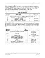
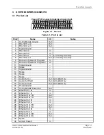
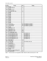
All connections to the GDL 69/69A are provided on the sub-miniature DB-78 connector labeled P691.
The antenna cable connection is provided on a TNC coaxial connector.
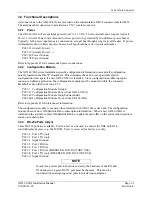
3.2.1 Power
The GDL 69/69A will accept input power from 9 to 33 VDC. The two aircraft power inputs (Aircraft
Power 1, Aircraft Power 2) are intended to allow power to be provided by two different power busses.
Typically, both power input pins are connected on a single bus through a single circuit breaker. If power
is obtained from two different power busses, each leg should have its own circuit breaker.
P691-35 Aircraft Power 1 +
P691-37 Aircraft Power 2 +
P691-20 Power Ground
P691-78 Power Ground
Refer to Appendix D for recommended power connections.
3.2.2 Configuration
Module
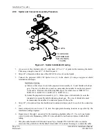
The GDL 69/69A stores installation-specific configuration information in an aircraft configuration
module located in the DB-78’s backshell. This eliminates the need to set up aircraft specific
configuration items again if a new GDL 69/69A is installed. Since configuration module input pins
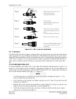
contain no lightning protection, the configuration module must be mounted within the connector
backshell as described in Section 2.5.3.
P691-1 Configuration Module Ground
P691-21 Configuration Module Power (from GDL 69/69A)
P691-40 Configuration Module Data (bi-directional)
P691-60 Configuration Module Clock (from GDL 69/69A)
Refer to Appendix D for interconnect information.
The configuration module is not used when installed with GDU 104x series units. The configuration
module does not store XM Satellite Radio subscription information. When a new GDL 69/69A is
installed in the aircraft, contact XM Satellite Radio to update the radio IDs on the current subscription or
start a new subscription.
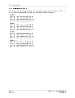
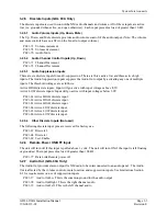
3.2.3 RS-232 Ports (Qty 3)
Three RS-232 ports are available. Ports 2 and 3 can be used to connect the GDL 69/69A to
control/display devices (e.g., the MX20). Port 1 is reserved for factory use only.
P691-2 Port 2 TX (out)
P691-3 Port 3 TX (out)
P691-4 Signal
Ground
P691-5 Port 2 RX (in)
P691-6 Port 3 RX (in)
P691-7 Port 1 RX (in) (RESERVED FOR FACTORY USE)
P691-8 Port 1 TX (out) (RESERVED FOR FACTORY USE)
P691-11 Signal Ground
NOTE
In order for a serial port to function correctly, the baud rate of the RX and
TX channels on a given RS232 port must be the same. This must be
considered when assigning serial ports to interfacing equipment.
Summary of Contents for GDL 69
Page 1: ...190 00355 02 June 2006 Revision E GDL 69 69A Installation Manual ...
Page 2: ...This Page Intentionally Left Blank ...
Page 69: ......
Page 70: ......

