Page vi
GDL 69/69A Installation Manual
Revision E
190-00355-02
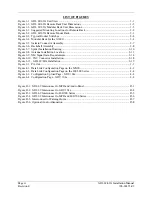
LIST OF FIGURES
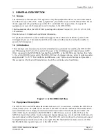
Figure 1-1. GDL 69/69A Unit View ........................................................................................................ 1-1
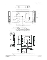
Figure 1-2. GDL 69/69A Remote Rack Unit Dimensions ....................................................................... 1-5
Figure 1-3. GDL 69/69A Modular Rack Unit Dimensions...................................................................... 1-5
Figure 2-1. Suggested Mounting Locations for Remote Rack ................................................................. 2-2
Figure 2-2. GDL 69/69A Remote Mount Rack........................................................................................ 2-3
Figure 2-3. Typical Rocker Switches ....................................................................................................... 2-4
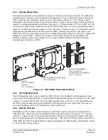
Figure 2-4. Modular Rack for the G1000................................................................................................. 2-4
Figure 2-5. Garmin Connector Assembly ................................................................................................ 2-7
Figure 2-6. Backshell Assembly .............................................................................................................. 2-8
Figure 2-7. Spider Installation Drawing................................................................................................. 2-10
Figure 2-8. Antenna Installation Location ............................................................................................. 2-13
Figure 2-9. XM Signal Gain Requirements............................................................................................ 2-14
Figure 2-10. TNC Connector Installation............................................................................................... 2-18
Figure 2-11. GDL 69/69A Installation ................................................................................................... 2-19
Figure 3-1. Pin Out................................................................................................................................... 3-1
Figure 4-1. Data Link Configuration Page on the MX20......................................................................... 4-3
Figure 4-2. Data Link Configuration Page on the 400/500 Series ........................................................... 4-4
Figure 4-3. Configuration Upload Page - GDU 104x .............................................................................. 4-4
Figure 4-4. Configuration Page – GDU 104x .......................................................................................... 4-4
Figure D-1. GDL 69 Interconnect to MFD and Audio Panel.................................................................. D-3
Figure D-2. GDL 69 Interconnect to GDU 104x .................................................................................... D-4
Figure D-3. GDL 69 Interconnect to 400/500 Series .............................................................................. D-5
Figure D-4. GDL 69 Interconnect to MFD and 400/500 Series.............................................................. D-6
Figure D-5. Interconnect to Warning Horns............................................................................................ D-7
Figure D-6. Optional Audio Attenuation ................................................................................................ D-8
Summary of Contents for GDL 69
Page 1: ...190 00355 02 June 2006 Revision E GDL 69 69A Installation Manual ...
Page 2: ...This Page Intentionally Left Blank ...
Page 69: ......
Page 70: ......

