background image

Garmin

®

 and the Garmin logo are trademarks of Garmin Ltd. or its subsidiaries, registered in the USA and other countries. GHP

, GHC

, Reactor

, and Shadow Drive

 are trademarks of Garmin Ltd. or its 

subsidiaries. These trademarks may not be used without the express permission of Garmin.
NMEA

®

, NMEA 2000

®

, and the NMEA 2000 logo are trademarks of the National Marine Electronics Association.

© 2014 Garmin Ltd. or its subsidiaries

www.garmin.com/support

Summary of Contents for GHP Reactor Hydraulic

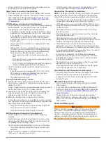
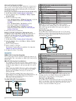
Page 1: ...e ties Waterproof wire connectors wire nuts or heat shrink tubing and a heat gun Marine sealant Marine corrosion inhibitor spray Portable or handheld compass to test for magnetic interference Hydrauli...

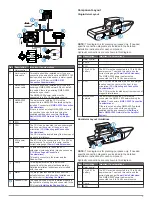
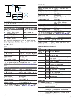
Page 2: ...he mounting surface The ECU must be located within 0 5 m 19 in of the pump The cables connecting the ECU to the pump cannot be extended The ECU must be mounted in a location where it will not be subme...

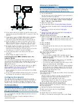
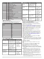
Page 3: ...and should be installed near the helm control Installing the Alarm Shadow Drive The Shadow Drive must be installed properly in the hydraulic steering line and connected to the CCU cable Installing the...

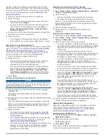
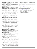
Page 4: ...hole as indicated on the template to begin cutting the mounting surface 4 Using the hole saw or rotary cutting tool cut the mounting surface along the inside of the dashed line indicated on the templ...

Page 5: ...ing system Refer to the instructions provided by the manufacturer of the steering system for more specific information about bleeding the system Before you bleed the hydraulic system you should verify...

Page 6: ...bare wire connections 4 Secure the alarm with cable ties or other mounting hardware not included NMEA 2000 and the Autopilot Components NOTICE If you have an existing NMEA 2000 network on your boat it...

Page 7: ...efore performing the Dockside Wizard to avoid damaging the steering system 1 Turn on the autopilot The first time you turn on the autopilot you are prompted to complete a short setup sequence 2 If the...

Page 8: ...tion Magnetic Environment Indicates the level of distortion of the Earth s magnetic field at the mounting location A value of 100 indicates the device experiences no magnetic interference at the mount...

Page 9: ...ration is correct and no further adjustments are necessary Adjusting the Acceleration Limiter Settings 1 Enable Dealer Mode Enabling Dealer Configuration 2 Select Menu Setup Dealer Autopilot Setup Aut...

Page 10: ...ion you need to identify the transmitting Tx and receiving Rx A and B wires When connecting NMEA 0183 devices with two transmitting and two receiving wires it is not necessary for the NMEA 2000 bus an...

Page 11: ...H W D 110 x 115 x 30 mm 4 33 x 4 53 x 1 18 in Dimensions with sun cover H W D 115 x 120 x 35 5 mm 4 53 x 4 72 x 1 40 in Weight without sun cover 247 g 8 71 oz Weight with sun cover 283 g 9 98 oz Temp...

Page 12: ...nds for 5 seconds The ECU shuts down Error Lost Communication Between ECU and CCU when the autopilot is engaged Communication between the CCU and the pump has timed out The helm control beeps and auto...

Page 13: ...eds This setting applies when the vessel operates above planing speed Steering System Settings To open the steering system settings select Menu Setup Dealer Autopilot Setup Steering System Setup Verif...

Page 14: ...s GHP GHC Reactor and Shadow Drive are trademarks of Garmin Ltd or its subsidiaries These trademarks may not be used without the express permission of Garmin NMEA NMEA 2000 and the NMEA 2000 logo are...

Reviews: