Page 1-2
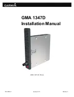
GMA 1347D Installation Manual
Revision C
190-00303-21
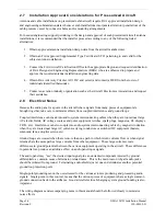
1.2.1 Features Summary
•
Logical front panel layout
•
LED annunciators indicate selected function
•
Five position intercom: pilot and four passengers
•
Two stereo headset amplifiers: one for the pilot and one for the passengers
•
Two stereo music source inputs
•
Two selectable intercom operational modes
•
VOX control for mic inputs
•
Automatic selection of radio audio source when corresponding mic is selected
•
MASQ
TM
Processing
•
COM swap function
•
TX indication
•
SmartMute
TM
marker audio muting
•
Speaker output for radios
•
Power-off fail safe connection for Pilot PTT, mic and Pilot’s Headset-Left to ON-SIDE COM
•
Digital audio interface
•
Voice Recorder
•
Cockpit Call (-20 only)
1.2.2 Interface Summary
The following is an interface summary for the GMA 1347D. See Section 4 and Appendix B for
connection details.
•
3 Transceiver Inputs/Outputs (Figure B-4)
•
1 Speaker Output (Figures B-1 and B-2)
•
2 Headset Outputs (Figure B-3)
•
5 Microphone Inputs (Figure B-3)
•
5 Receiver Inputs (Figure B-4)
•
4 Unswitched Inputs (Figure B-4)
•
6 Digital Audio Inputs (Figure B-5)
•
2 Aircraft Power Inputs (Figures B-1 and B-2)
•
Discrete Inputs/Outputs (Figure B-6)
•
PFD/MFD Reversionary Mode outputs (Figures B-1 and B-2)
•
2 RS-232 Inputs/Outputs (Figure B-5)
•
Marker Beacon Antenna Input (Figures B-1 and B-2)
•
External Marker Beacon Lamp Driver Outputs (Figure B-6)

