background image

190-01879-11

GMA 245/245R Installation Manual

Rev. 6

Page v

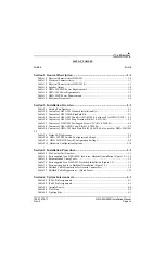
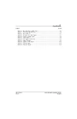
LIST OF FIGURES

FIGURE

PAGE

Section 1 General Description ...........................................................................1-1

Section 2 Installation Overview.........................................................................2-1

Figure 2-1  GMA 245R Bluetooth Transceiver Location...................................................... 2-4
Figure 2-2  SD Card Slot and DIP Switch Locations ............................................................ 2-7
Figure 2-3  Front Panel Configuration................................................................................... 2-9
Figure 2-4  GMA 245 Unit Rack (115-00262-00)............................................................... 2-13
Figure 2-5  GMA 245R w/Mounting Brackets on Front and Back ..................................... 2-14
Figure 2-6  GMA 245R w/Mounting Brackets on Sides ..................................................... 2-14

Section 3 Installation Procedure........................................................................3-1

Figure 3-1  GMA 245R Jackscrew Backshell Assembly ...................................................... 3-4
Figure 3-2  GMA 245 Shield Block Backshell Assembly..................................................... 3-5
Figure 3-3   Method A.1 for Shield Termination................................................................... 3-6
Figure 3-4   Insulation/Contact Clearance ............................................................................. 3-8
Figure 3-5   Method A.2 (Daisy Chain) for Shield Termination ......................................... 3-10
Figure 3-6   Method B.1 (Quick Term) for Shield Termination.......................................... 3-12
Figure 3-7  Method B.2 (Daisy Chain-Quick Term) for Shield Termination...................... 3-13
Figure 3-8   Daisy Chain between Methods A and B .......................................................... 3-14
Figure 3-9  Jackscrew D-Sub Spliced Signal Wire illustration ........................................... 3-15
Figure 3-10  Shield Block D-Sub Spliced Signal Wire illustration..................................... 3-16
Figure 3-11  Rear View of Rack and Connectors ................................................................ 3-17
Figure 3-12  GMA 245 Audio Shield Termination (top and bottom) ................................. 3-17
Figure 3-13  GMA 245R Audio Shield Termination (top and bottom)............................... 3-18
Figure 3-14  Diagnostics Mode ........................................................................................... 3-21

Section 4 System Interconnects .........................................................................4-1

Figure 4-1  Rear View of Backplate and Connectors ............................................................ 4-1
Figure 4-2  Rear Connectors J2401 & J2402, Viewed from Back of Unit............................ 4-1

Section A Installation Considerations for Upgrading from a Garmin 

GMA 240 ............................................................................................A-1

Figure A-1  GMA 240 to GMA 245 Retrofit Connections................................................... A-2

Appendix B Outline and Installation Drawings .............................................B-1

Figure B-1  GMA 245 Outline Drawing................................................................................B-1
Figure B-2  GMA 245 Installation Drawing..........................................................................B-2
Figure B-3   GMA 245R Outline Drawing, End Mount Bracket Installation .......................B-3
Figure B-4  GMA 245/245R Outline Drawing, Side Mount Bracket Installation.................B-4
Figure B-5  GMA 245/245R Installation Drawing, End and Side Bracket Mounting ..........B-5

Summary of Contents for GMA 245

Page 1: ...190 01879 11 August 2017 Revision 6 GMA 245 245R Installation Manual ...

Page 2: ...inted copy of this manual or revision must contain the complete text of this copyright notice and provided further that any unauthorized commercial distribution of this manual or any revision hereto is strictly prohibited Garmin International Inc 1200 E 151st Street Olathe KS 66062 USA Aviation Panel Mount Technical Support Line Toll Free 1 888 606 5482 Garmin Europe Ltd Liberty House Hounsdown Bu...

Page 3: ...ONS OF WARNINGS CAUTIONS AND NOTES WARNING This product its packaging and its components contain chemicals known to the State of California to cause cancer birth defects or reproductive harm This Notice is being provided in accordance with California s Proposition 65 If you have any questions or would like additional information please refer to our web site at www garmin com prop65 NOTE Throughout...

Page 4: ... multi transmitter product procedures 2 IC Contains IC 5123A BGTWT32I NOTE This device complies with Innovation Science and Economic Development Canada license exempt RSS standard s Operation is subject to the following two conditions 1 this device may not cause interference and 2 this device must accept any interference including interference that may cause undesired operation of the device Cet a...

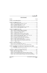
Page 5: ...oling Air 2 5 2 9 Configuration and Adjustment Options 2 6 2 10 Updating Software 2 11 2 11 Noise 2 12 2 12 Mounting Requirements 2 13 Section 3 Installation Procedure 3 1 3 1 Unpacking Unit 3 1 3 2 Electrical Connections 3 1 3 3 Jackscrew and Shield Block Backshell Installation Instructions 3 2 3 4 Backshell Assembly 3 17 3 5 Audio Shield Termination 3 17 3 6 Unit Installation 3 18 3 7 Post Insta...

Page 6: ...ection A Installation Considerations for Upgrading from a Garmin GMA 240 A 1 A 1 Mechanical Considerations A 1 A 2 Electrical Considerations A 1 A 3 GMA 240 to GMA 245 Retrofit Connections A 2 Appendix B Outline and Installation Drawings B 1 Appendix C Interconnect Drawings C 1 ...

Page 7: ... for Shield Termination 3 13 Figure 3 8 Daisy Chain between Methods A and B 3 14 Figure 3 9 Jackscrew D Sub Spliced Signal Wire illustration 3 15 Figure 3 10 Shield Block D Sub Spliced Signal Wire illustration 3 16 Figure 3 11 Rear View of Rack and Connectors 3 17 Figure 3 12 GMA 245 Audio Shield Termination top and bottom 3 17 Figure 3 13 GMA 245R Audio Shield Termination top and bottom 3 18 Figu...

Page 8: ...C 1 Figure C 2 J2401 Connector Example Interconnect Drawing C 2 Figure C 3 J2402 Connector Example Interconnect Drawing C 3 Figure C 4 Lighting Bus Example Interconnect Drawing C 4 Figure C 5 Mono Audio Example Interconnect Drawing C 5 Figure C 6 Four Passenger Headset Wiring Example Interconnect Drawing C 6 Figure C 7 J2401 J2402 Connector Layout Drawing C 7 ...

Page 9: ...ws D 011 02650 03 2 2 Table 2 8 Contents of GMA 245R Conn Kit 011 03828 00 2 2 Table 2 4 Contents of GMA 245 Back Plate Kit 011 00678 00 also used for GMA 240 340 2 2 Table 2 9 Status LED Indications 2 4 Table 2 10 GMA 245 DIP Switch Configuration Settings 2 7 Table 2 11 GMA 245R DIP Switch Configuration Settings 2 8 Table 2 12 Hardwire Configuration Options 2 10 Section 3 Installation Procedure 3...

Page 10: ...OM Audio and Mic Keys 4 6 Table 4 8 Alert Audio I O 4 7 Table 4 9 AUX and NAV Audio Inputs 4 7 Table 4 10 Failsafe Warning Audio 4 8 Table 4 11 Music Inputs 4 8 Table 4 12 TEL Audio XCVR 3 I O 4 9 Table 4 13 Headset Outputs 4 9 Table 4 14 Speaker Audio Output 4 10 Table 4 15 Discrete Inputs 4 10 Table 4 16 Discrete Outputs 4 10 ...

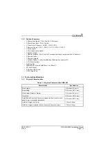
Page 11: ... to help in situations where a COM transmission may need to be heard again In addition the GMA 245 uses Bluetooth for listening to music and making phone calls or sending headset audio to a VIRB XE and a 10 Watt USB charge port for phones and tablets Other features include intuitive configuration a lighting bus input SD Card socket for code loads and Bluetooth firmware updates an 8 position DIP sw...

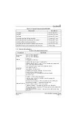
Page 12: ...ode or power off 1 CAN Bus Interface Lighting Bus Bluetooth not shared with Music 1 or Music 2 SD Card Socket 8 Position DIP Switch USB Charge Port 1 3 Technical Specifications 1 3 1 Physical Characteristics Table 1 1 Physical Characteristics GMA 245 Characteristic Specification Bezel Height 1 30 inches 33 0 mm Bezel Width 6 30 inches 160 0 mm Rack Height Dimple to Dimple 1 33 inches 34 0 mm Rack ...

Page 13: ... Feet Audio Panel Functions Dedicated Transceiver inputs 3 including TEL Dedicated Receiver inputs 5 AUX 1 2 and 3 selected with a single button NAV 1 and 2 independently selectable Alert unswitched inputs 4 each with configurable volume Input impedance 600 Ω Input isolation 60 dB minimum Alert Receiver Transceiver bandwidth 100 Hz to 6 5 kHz Special functions Fail safe operation All inputs use MA...

Page 14: ...tooth Connectivity Bluetooth 3 00 Compliant allows music cell phone calls and interface with the VIRB XE action camera Bluetooth supports HFP including HFP v1 6 Wide Band Speech mode A2DP and AVRCP The GMA stores 10 paired devices and overwrites the least recently connected device when a new device is paired Only 1 Bluetooth connection allowed at one time The VIRB XE cannot be connected when using...

Page 15: ...77 A 14 VDC 0 40 A 28 VDC 10 78 W 14 VDC 11 20 W 28 VDC Maximum Current with no USB charge port connection 1 11 A 14 VDC 0 87 A 28 VDC 15 54 W 14 VDC 24 36 W 28 VDC Maximum Current with USB charge port connection 2 31 A 14 VDC 1 45 A 28 VDC 32 34 W 14 VDC 40 60 W 28 VDC Unit current drawn with power applied no audio and minimum lighting Table 1 7 GMA 245R Power Requirements Characteristic Current ...

Page 16: ...ces of additional information for installing the GMA 245 The installer should read all referenced materials along with this manual before attempting installation Table 1 8 Reference Documents Part Number Document 190 01115 01 G3X Installation Manual 190 01754 00 G3X Touch Pilot s Guide 190 01879 10 GMA 245 Pilot s Guide ...

Page 17: ... 2 2 Installation Materials 2 2 1 Unit Configurations 2 3 Available Accessories 2 3 1 Standard Accessories Table 2 1 Catalog Part Numbers Model Catalog Part Number Unit Only Part Number GMA 245 Unit Only 010 01318 00 011 03519 00 GMA 245 Standard includes items in Table 2 2 010 01318 01 011 03519 00 GMA 245R Unit Only 010 01471 00 011 03784 00 GMA 245R Standard Kit includes items in Table 2 3 010 ...

Page 18: ... Connector Mil Crimp 44 ckt 330 00185 44 2 Contact Pin Mil Crimp Size 22D 336 00021 00 94 Table 2 6 Contents of GMA 245 Ring Terminal Kit 011 04151 00 Item Part Number Quantity Screw 8 32 x 0 312 PHP SS P 211 60209 09 8 Washer Split Lock Size 8 212 00018 04 8 Washer Flat Non Std SS ID 0 195 OD 0 354 212 20065 00 8 Table 2 7 Contents of GMA 245 Pre bagged Screws D 011 02650 03 Item Part Number Quan...

Page 19: ...Tie Wraps or Lacing Cord Ring Terminals for grounding 8 size Yellow Blue and Pink Silicon Fusion Tape GPN 249 00114 00 to wrap the cable bundle Silicone fusion tape is available at most major suppliers like Mouser Digi key and Home Depot Solder Sleeves for terminating the shields of the cable to the GMA backshell See Section 3 3 for part numbers Optional USB Type A Panel Mount Bulkhead Jack to Typ...

Page 20: ...rformance can be also be obtained with the GMA 245R remote mount if mounting location and orientation are selected to keep the instrument panel and other aircraft metal structures from blocking the Bluetooth signal GMA 245R mounting location orientation will vary for each installation depending on aircraft body type metal or fiberglass and the surrounding structures equipment The GMA 245R Bluetoot...

Page 21: ...C for wire gauge guidance In some cases a larger gauge wire such as AWG 18 or 20 may be needed for power connections If using AWG 18 barrel contacts ensure that no two contacts are mounted directly adjacent to each other This minimizes the risk of contacts touching and shorting to adjacent pins and to ground Use wire and cable meeting the applicable aviation regulation When routing wire and cable ...

Page 22: ... low level noise from being passed to the headset ear speakers this is known as squelching or muting the audio To break or open squelch means that enough audio signal is present that the signal is passed through and can be heard Increasing this setting increases the signal level required to break open squelch If needed adjust the MASQ SQ level so the audio background noise is muted 2 9 2 High Cock...

Page 23: ...NOT be active 2 PILOT IN RIGHT SEAT This setting is for intercom 3D audio Normally the Pilot will be positioned to the left in the Copilot s headset and the Copilot will be positioned to the right in the Pilot s headset When set to ON this setting reverses that so the Pilot is positioned to the right in the Copilot s headset and the Copilot is positioned to the left in the Pilot s headset 3 MUTE O...

Page 24: ...s for intercom 3D audio Normally the Pilot will be positioned to the left in the Copilot s headset and the Copilot will be positioned to the right in the Pilot s headset When set to ON this setting reverses that so the Pilot is positioned to the right in the Copilot s headset and the Copilot is positioned to the left in the Pilot s headset 3 MUTE ON COM TX When set to ON the monitored COM radio is...

Page 25: ...nd change the state If the option is enabled the PILOT key is lit solid and the CREW key flashes indicating that the CREW key can be pushed to disable the option Likewise if the option is disabled the CREW key is lit solid and the PILOT key flashes indicating that the PILOT key can be pushed to enable the option The Level Bar is not used when in the options mode When in configuration mode the LEDs...

Page 26: ... selected COM audio or when transmitting on the MIC selected COM This output can be used to connect to other devices to inhibit other devices from playing audio into the GMA while there is COM activity J2402 13 PASSENGER ICS KEY Input If DIP switch 1 is on this active low input when grounded will allow microphone audio to the intercom from Passenger MIC J2402 20 COM SWAP Input When grounded the MI...

Page 27: ... Vista Windows 7 or Windows 10 There is no Mac support at this time 1 Go to the GMA 245 web page on Garmin s website 2 Download the GMA 245 software to your PC 3 Ensure that an SD card Garmin recommends a Sandisk brand 4GB SD card is connected to the PC in the SD card slot 4 Run the executable file that was downloaded and follow the prompts on the screen to create the software loader card 5 After ...

Page 28: ...t be taken to minimize effects from coupled interference and ground loops Coupled interference can sneak into audio system interconnecting cables when they are routed near large AC electric fields AC voltage sources and pulse equipment strobes spark plugs magnetos EL displays CRTs etc Interference can also couple into audio system interconnecting cables by magnetic induction when they are routed n...

Page 29: ...re 2 4 See Section 3 6 for installation instructions NOTE Rear support is recommended to ensure a sturdy mount CAUTION The top cover of the unit has a connector number 1 and 2 stamped into it and centered in front of each connector The 011 00678 00 backplate also has a stamped number on it To prevent damage to the unit verify the connectors are positioned correctly connector 1 is connected in posi...

Page 30: ... Brackets on Front and Back NOTE The GMA 245R is shipped in the configuration shown in Figure 2 5 Figure 2 6 GMA 245R w Mounting Brackets on Sides NOTE The side mounting bracket show in Figure 2 6 is an additional part included in the standard kit and is also available as an optional accessory ...

Page 31: ...ors see Figure 3 11 Section 4 defines the electrical characteristics of all input and output signals Required connector and associated hardware are supplied in the connector kits Refer to Section 2 3 for the GMA 245 and GMA 245R standard kit part numbers that contain the necessary hardware See Appendix C for interconnect wiring diagrams CAUTION Check wiring connections for errors before inserting ...

Page 32: ...ed in Table 3 5 are to be provided by the installer The items listed in Table 3 3 are provided in the GMA 245R Connector Kit Table 2 8 Table 3 2 Recommended Crimp Tools Manufacturer Hand Crimping Tool 18 20 AWG 22 28 AWG Positioner Insertion Extraction Tool Note 2 Positioner Insertion Extraction Tool Military P N M22520 2 01 N A M81969 1 04 M22520 2 09 M81969 1 04 Positronic 9507 9502 11 M81969 1 ...

Page 33: ...ty D Sub Connector Mil Crimp 44 ckt 330 00185 44 17 Screw 4 40x 250 FLHP100 SS P 211 63234 08 18 Adapter Ring Terminal Shell SZ 1 2 117 00147 00 19 Screw 4 40x 437 FLHP100 SS P Nylon 211 63234 11 GMA 245 Shield Block Backshell only Table 3 5 Parts not supplied for a Backshell Installation Figure 3 1 Item Description GPN or MIL spec 2 Multiple Conductor Shielded Cable 2 conductor shown in Figure 3 ...

Page 34: ...190 01879 11 GMA 245 245R Installation Manual Rev 6 Page 3 4 Figure 3 1 GMA 245R Jackscrew Backshell Assembly ...

Page 35: ...stallation Manual Rev 6 Page 3 5 Figure 3 2 GMA 245 Shield Block Backshell Assembly 1 2 2 4 AR AR 5 AR AR 6 AR AR 7 AR AR 9 AR AR AR AR AR AR 10 10 AR AR 17 17 2 15 15 3 14 14 8 AR AR 13 13 AR AR 2 16 16 3 12 12 11 11 19 19 18 18 ...

Page 36: ... in the jacket to expose the shield item 4 Figure 3 3 Use caution when cutting the jacket to avoid damaging the individual braids of the shield When dealing with a densely populated connector with many cables it may prove beneficial to stagger the windows throughout the Window Min to Window Max range If staggering is not needed the Ideal Window length is recommended Suggested tools to accomplish t...

Page 37: ...ductors present in the cable and the Flat Braid item 4 Figure 3 3 to be attached Solder Sleeves with pre installed Flat Braid A preferred solder sleeve would be the Raychem S03 Series with the thermochromic temperature indicator S03 02 R 9035 100 S03 03 R 9035 100 S03 04 R 9035 100 These solder sleeves come with a pre installed braid and effectively take the place of items 3 and 4 Figure 3 3 For d...

Page 38: ... the insulated center conductors Figure 3 3 The Ideal Float length may be best to build optimally Preferred Method The jacket and shield should be cut off at the same point so no shield is exposed Slide 0 75 inches minimum of Teflon heat shrinkable tubing item 5 Figure 3 3 onto the cable and use a heat gun to shrink the tubing The chosen size of heat shrinkage tubing must accommodate the number of...

Page 39: ...raid is needed for this connector a Ring terminal 8 insulated 18 22 AWG MS25036 149 can accommodate this single Flat Braid If more braids exist for this connector than two per ring terminal it is permissible to terminate three braids per ring terminal This will necessitate the use of a Ring terminal 8 insulated 10 12 AWG MS25036 156 9 Repeat steps 2 through 8 as needed for the remaining shielded c...

Page 40: ...han three per ring terminal it is allowable to daisy chain a maximum of two shields together before coming to the ring terminal Figure 3 5 All other restrictions and instructions for the shield termination technique set forth for Method A 1 are still applicable NOTE The maximum length of the combined braids should be approximately 4 inches Figure 3 5 Method A 2 Daisy Chain for Shield Termination ...

Page 41: ...ollowing At the end of the shielded cable item 2 Figure 3 1 or Figure 3 2 strip Quick Term Min to Quick Term Max Table 3 7 length of the jacket to expose the shield Next trim the shield so that at most 0 35 inches remains extending beyond the insulating jacket Fold this remaining shield back over the jacket Connect a Flat Braid item 4 Figure 3 1 or Figure 3 2 to the folded back shield of the prepa...

Page 42: ...imum of 0 75 inches of Teflon heat shrinkable tubing item 3 Figure 3 6 onto the prepared wire assembly and shrink using a heat gun The chosen size of heat shrinkage tubing must accommodate both the number of conductors present in the cable as well as the Flat Braid item 4 Figure 3 6 to be attached Teflon Heat Shrinkable Tubing Reference the following MIL Spec for general Teflon heat shrinkable tub...

Page 43: ...hree per ring terminal it is allowable to daisy chain a maximum of two shields together before coming to the ring terminal Figure 3 7 All other restrictions and instructions for the shield termination technique set forth for Method B 1 are still applicable NOTE The maximum length of the combined braids should be approximately 4 inches Figure 3 7 Method B 2 Daisy Chain Quick Term for Shield Termina...

Page 44: ...igure 3 8 Daisy Chain between Methods A and B 3 3 7 Splicing Signal Wires Refer to Figure 3 9 for GMA 245R installations or to Figure 3 10 for GMA 245 installations NOTE Figure 3 9 and Figure 3 10 illustrate that a splice must be made within a 3 inch window from outside the edge of clamp to the end of the 3 inch max mark WARNING Keep the splice out of the backshell for pin extraction and outside o...

Page 45: ...190 01879 11 GMA 245 245R Installation Manual Rev 6 Page 3 15 Figure 3 9 Jackscrew D Sub Spliced Signal Wire illustration ...

Page 46: ...al Rev 6 Page 3 16 Figure 3 10 Shield Block D Sub Spliced Signal Wire illustration 0 75inchesMIN SHRINKABLE TUBING ENDOFSHIELDBLOCK 4inchesMAX 0 35inchesMAX WINDOWSIZE SLEEVEEDGE EDGEOFSTRAINRELIEF OUTEREDGEOFSPLICE 3inchesMAX SPLICE OUTERSOLDER ...

Page 47: ...ousing using the Shield Block To assemble the backshell connectors and grounding system refer to instructions provided in the Section 3 3 Figure 3 11 Rear View of Rack and Connectors 3 5 Audio Shield Termination For audio shield terminations the cable shield terminations should be tied to the backshell using ring terminals and the supplied 8 screws with lock and flat washer per Figure 3 12 and Fig...

Page 48: ...the screws provided in the connector kit Figure B 2 3 Mount the GMA 245 rack to the GMA rack as shown on the installation drawing 4 Assemble the rear plate into the GMA 245 unit rack 5 Insert the GMA 245 into the rack noting proper orientation as shown on the installation drawing 6 Lock the GMA 245 in place using a 3 32 Allen tool 3 6 2 GMA 245R Installation For final installation and assembly ref...

Page 49: ...of a true mono headset is required for this test not a stereo headset with a mono stereo switch because headset manufactures differ on how they accomplish this switching This will guarantee the condition of the right channel ring terminal being shorted to the return sleeve terminal by the mono headset s plug This short occurs because of the physical design of the headset plug contacts and is an in...

Page 50: ... is selected as the music source and MUSIC LED is on Verify that music volume adjustment is working properly for Pilot and Copilot Passengers if passenger headsets are wired 3 Select an audio source to COM 1 and verify that the sound is muted by active COM 1 audio when Radio Mute Music is selected and by intercom audio when ICS Mute Music is selected 4 Connect a stereo music source to MUSIC 2 Veri...

Page 51: ...ostics Information The GMA 245 is capable of displaying diagnostics information while in normal mode of operation To show the diagnostics information press the PLAY button for five seconds While still holding the PLAY button all button annunciators will turn off except for those associated with certain diagnostic states All button annunciators are off if no diagnostic information is available The ...

Page 52: ...r 5 seconds 2 An audio clip will be heard in the headset that says Bluetooth Disabled 3 To re enable Bluetooth without power cycling press and hold the TEL key for 5 seconds 4 An audio clip will be heard in the headset that says Bluetooth Enabled NOTE Once disabled the GMA 245 Bluetooth function does not remain disabled after powercycling The GMA 245 Bluetooth function is always enabled following ...

Page 53: ...ck of Unit J2401 and J2402 pins are configured as shown in Figure 4 2 J2401 and J2402 pin assignments are given in Table 4 1 Table 4 2 and Appendix C Following the Table 4 1 Table 4 2 additional tables group pin connections by function An asterisk following a signal name denotes that the signal is active low logic Active low inputs are connected to ground to activate Active low outputs sink curren...

Page 54: ...5 AUDIO IN HI AUX 3 IN 24 COM ACTIVE OUT OUT 25 RESERVED 26 RESERVED 27 RESERVED 28 RESERVED 29 ALERT 3 AUDIO IN HI IN 30 COM 2 MIC KEY OUT OUT 31 ALERT 1 AUDIO IN HI IN 32 ALERT 1 AUDIO IN LO 33 PILOT MIC AUDIO IN HI IN 34 PILOT MIC KEY IN IN 35 PILOT MIC AUDIO IN LO 36 CAN BUS HI I O 37 CAN BUS LO I O 38 RESERVED 39 RESERVED 40 PASS HEADSET AUDIO OUT LEFT OUT 41 PASS HEADSET AUDIO OUT RIGHT OUT ...

Page 55: ...POWER GROUND 12 RESERVED 13 PASSENGER ICS KEY IN 14 ALERT 2 LO FAILSAFE AUDIO IN LO 15 ALERT 2 AUDIO IN HI IN 16 PILOT HEADSET AUDIO OUT LEFT OUT 17 RESERVED 18 RESERVED 19 RESERVED 20 COM SWAP IN 21 GROUND 22 PLAY KEY IN 23 MUSIC 1 IN LEFT IN 24 MUSIC 1 IN RIGHT IN 25 MUSIC 1 IN LO 26 MUSIC 2 IN LEFT IN 27 MUSIC 2 IN RIGHT IN 28 MUSIC 2 IN LO 29 FAILSAFE WARN AUDIO IN HI IN 30 COPILOT ICS KEY IN ...

Page 56: ...work 2 0 B and complies with ISO 11898 36 PASS 1 MIC AUDIO IN LO 37 PASS 2 MIC AUDIO IN HI IN 38 PASS 2 MIC AUDIO IN LO 39 PASS 3 MIC AUDIO IN HI IN 40 PASS 3 MIC AUDIO IN LO 41 PASS 4 MIC AUDIO IN HI IN 42 PASS 4 MIC AUDIO IN LO 43 SPEAKER AUDIO OUT LO 44 SPEAKER AUDIO OUT HI OUT Denotes Active Low Inputs ground to activate Outputs grounded when active Table 4 3 Aircraft Power Pin Connector Pin N...

Page 57: ... the resistor connection for the 9 pin D sub terminator in this kit This kit allows easy removal of the termination for allowing CAN Bus changes in the aircraft installation 4 5 Lighting Bus The GMA 245 can be configured to track a 14 or 28 Vdc lighting bus using these inputs Refer to Appendix C for lighting interconnections Backlighting refers only to the lighting of the text labels on the front ...

Page 58: ... J2402 PASS 2 MIC AUDIO IN HI Passenger 2 Mic audio and ground reference IN 38 J2402 PASS 2 MIC AUDIO IN LO 39 J2402 PASS 3 MIC AUDIO IN HI Passenger 3 Mic audio and ground reference IN 40 J2402 PASS 3 MIC AUDIO IN LO 41 J2402 PASS 4 MIC AUDIO IN HI Passenger 4 Mic audio and ground reference IN 42 J2402 PASS 4 MIC AUDIO IN LO Denotes Active Low Ground to activate Table 4 7 COM Audio and Mic Keys P...

Page 59: ... 44 J2401 ALERT 4 AUDIO IN HI Alert 4 Audio Input IN Table 4 9 AUX and NAV Audio Inputs Pin Connector Pin Name Description I O 21 J2401 RCVR 3 AUDIO IN HI AUX 1 RCVR 3 AUX 1 Audio Input IN 22 J2401 RCVR 3 AUDIO IN LO AUX 1 Ground Reference for RCVR 3 AUX 1 Input 7 J2401 RCVR 4 AUDIO IN HI AUX 2 RCVR 4 AUX 2 Audio Input IN 8 J2401 RCVR 4 AUDIO IN LO AUX 2 Ground Reference for RCVR 4 AUX 2 Input 23 ...

Page 60: ...sic Inputs The MUSIC LO signals are not the same reference as other ground connections The MUSIC LO signals should be used as part of a differential pair along with the MUSIC RIGHT and MUSIC LEFT signals If the MUSIC LO signal is tied to a ground connection the music will contain noise and the audio quality will be degraded Table 4 10 Failsafe Warning Audio Pin Connector Pin Name Description I O 2...

Page 61: ...dset output to protect the GMA 245 headset output from driving a signal into a short and also for internal audio routing determined by the mono headset plugged into the headset jack In aircraft systems that use mono headset jacks and are wired correctly if used mono jacks should always use left channel audio and headset lo 3D audio will not be available and only left channel audio for music inputs...

Page 62: ...OUT 41 J2401 PASS HEADSET AUDIO OUT RIGHT OUT 42 J2401 PASS HEADSET AUDIO OUT LO Table 4 14 Speaker Audio Output Pin Connector Pin Name Description I O 43 J2402 SPEAKER AUDIO OUT LO Speaker Audio Output Ground Reference 44 J2402 SPEAKER AUDIO OUT HI Speaker Audio Output Hi OUT Table 4 15 Discrete Inputs Pin Connector Pin Name Description I O 16 J2401 PILOT ICS KEY Discrete Input IN 13 J2402 PASSEN...

Page 63: ... to Section 2 2 of this manual for a list of installation materials The GMA 240 connectors are compatible and may be reused If replacing a GMA 240 with a GMA 245 the GMA 240 330 00220 25 connector backshells can be reused However grounding the wire shields to the GMA will be easier with the Garmin backshells in GPN 011 02302 00 The Garmin backshells also offer higher immunity to HIRF Current insta...

Page 64: ... 42 44 43 19 22 PLAY KEY IN 30 COPILOT ICS KEY IN GMA 240 RETROFIT NOTES FOR INSTALLING GMA 245 BUTTON PRESS TONE ENABLE NO CONNECT NO CONNECT NO CONNECT NO CONNECT NO CONNECT NO CONNECT 39 40 41 42 44 43 19 22 NO CONNECT 30 MUTE ON COM TX IN J2402 P2402 PASSENGER ICS KEY IN COPILOT ICS KEY IN J2401 P2401 36 37 29 23 MASQ INHIBIT IN 16 NO CONNECT 24 CREW ISO IN NO CONNECT GMA 240 RETROFIT NOTES FO...

Page 65: ...190 01879 11 GMA 245 245R Installation Manual Revision 6 Page B 1 APPENDIX B OUTLINE AND INSTALLATION DRAWINGS Figure B 1 GMA 245 Outline Drawing ...

Page 66: ...190 01879 11 GMA 245 245R Installation Manual Revision 6 Page B 2 APPENDIX B OUTLINE AND INSTALLATION DRAWINGS Figure B 2 GMA 245 Installation Drawing ...

Page 67: ...190 01879 11 GMA 245 245R Installation Manual Revision 6 Page B 3 APPENDIX B OUTLINE AND INSTALLATION DRAWINGS Figure B 3 GMA 245R Outline Drawing End Mount Bracket Installation ...

Page 68: ...190 01879 11 GMA 245 245R Installation Manual Revision 6 Page B 4 APPENDIX B OUTLINE AND INSTALLATION DRAWINGS Figure B 4 GMA 245 245R Outline Drawing Side Mount Bracket Installation ...

Page 69: ...5R Installation Manual Revision 6 Page B 5 APPENDIX B OUTLINE AND INSTALLATION DRAWINGS Figure B 5 GMA 245 245R Installation Drawing End and Side Bracket Mounting END MOUNT BRACKET INSTALLATION SIDE MOUNT BRACKET INSTALLATION ...

Page 70: ...M 10 WATT SPEAKER 1 UNLESS OTHERWISE INDICATED ALL SHIELDS MUST BE TERMINATED AT THE GMA 245 END ONLY ALL SHIELDS ARE TIED TO THE BACKSHELL USING RING TERMINALS FOR GMA 245 USE THE RING TERMINAL ADAPTERS PROVIDED FOR THE BACKSHELLS IN THE CONNECTOR KIT FOR GMA 245R CONNECT RING TERMINALS TO THE BACKSHELLS FOR BOTH UNITS 8 SCREWS WASHERS AND SPLIT WASHERS ARE PROVIDED ALL HEADSET MICROPHONE AND MUS...

Page 71: ...V 2 AUDIO IN HI NAV 2 AUDIO IN LO AUX 1 AUDIO IN HI AUX 1 AUDIO IN LO AUX 2 AUDIO IN HI AUX 2 AUDIO IN LO ALERT 1 AUDIO IN HI ALERT 1 AUDIO IN LO ALERT 4 AUDIO IN HI TEL MIC AUDIO OUT HI ALERT 3 AUDIO IN HI ALERT 3 4 AUX 3 AUDIO LO AUX 3 AUDIO IN HI ALERT 3 4 AUX 3 AUDIO LO ALERT 3 4 AUX 3 AUDIO LO PILOT MIC AUDIO IN LO PILOT MIC AUDIO IN HI SEE NOTE 5 SEE NOTE 12 SEE NOTE 13 SEE NOTE 13 SEE NOTE ...

Page 72: ...raft Power Bus 5A 1 31 16 2 4 3 34 33 32 35 36 37 38 39 40 41 42 24 23 25 44 43 20 12 19 8 9 10 11 15 29 22 ALERT 2 AUDIO IN HI FAILSAFE WARN AUDIO IN HI PLAY KEY IN 30 COPILOT ICS KEY IN 14 NO CONNECT NO CONNECT 17 18 MUSIC 2 IN LO MUSIC 2 IN RIGHT MUSIC 2 IN LEFT 27 26 28 Alert 2 Audio J2402 P2402 COPILOT PTT Failsafe Audio GMA 245 SEE NOTE 5 6 ALERT 2 FAILSAFE AUDIO LO PASSENGER ICS KEY IN 13 U...

Page 73: ...V HI 5 7 TO 14 VOLT LIGHTING BUS HI TO 14 VOLT LIGHTING BUS LO LIGHTING BUS 14V HI 28V LO 6 14 VOLT LIGHTING BUS LIGHTING BUS 14V LO 28V LO LIGHTING BUS 14V HI 28V HI 5 7 TO 28 VOLT LIGHTING BUS HI TO 28 VOLT LIGHTING BUS LO LIGHTING BUS 14V HI 28V LO 6 28 VOLT LIGHTING BUS OR P2402 IF NEITHER OF THE ABOVE LIGHTING BUS CONFIGURATIONS ARE WIRED THE UNIT WILL DEFAULT TO USE THE DISPLAY PHOTOCELL FOR...

Page 74: ...OUT HI MONO CONNECTIONS PILOT HEADSET LO PILOT HEADSET RIGHT PILOT HEADSET LEFT 1 31 16 NC COPILOT HEADSET LO COPILOT HEADSET RIGHT COPILOT HEADSET LEFT 2 4 3 MUSIC 1 IN LO MUSIC 1 IN RIGHT MUSIC 1 IN LEFT 24 23 25 MUSIC 2 IN LO MUSIC 2 IN RIGHT MUSIC 2 IN LEFT 27 26 28 NC MONO AUDIO OUT LO MONO AUDIO SOURCE MONO AUDIO OUT HI NC PILOT HEADSET JACK NOTE 5 15 COPILOT HEADSET JACK NOTE 5 15 GMA 245 J...

Page 75: ...on 6 Page C 6 APPENDIX C INTERCONNECT DRAWINGS Figure C 6 Four Passenger Headset Wiring Example Interconnect Drawing PASSENGER HEADSET PARALLEL WIRING PASS HEADSET LO PASS HEADSET RIGHT PASS HEADSET LEFT 41 40 42 NOTE 5 UP TO 4 JACKS J2401 P2401 GMA 245 ...

Page 76: ...DIO IN LO 18 NAV 1 AUDIO IN LO 16 DISCRETE 1 INPUT PILOT ICS KEY 1 RESERVED 31 ALERT 1 AUDIO IN HI 17 NAV 1 AUDIO IN HI GMA 245 J2401 30 DISCRETE 6 INPUT COPIILOT ICS KEY 15 ALERT 2 AUDIO IN HI 14 ALERT 2 LO FAILSAFE AUDIO IN LO 44 SPEAKER AUDIO OUT HI 13 PASS ICS KEY 42 PASS 4 MIC AUDIO IN LO 28 MUSIC 2 IN LO 43 SPEAKER AUDIO OUT LO 29 FAILSAFE WARN AUDIO IN HI 27 MUSIC 2 IN RIGHT 41 PASS 4 MIC A...

Reviews: