background image

GMR 18/24 Marine Radar Installation Instructions

5

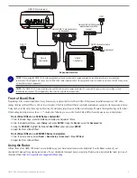
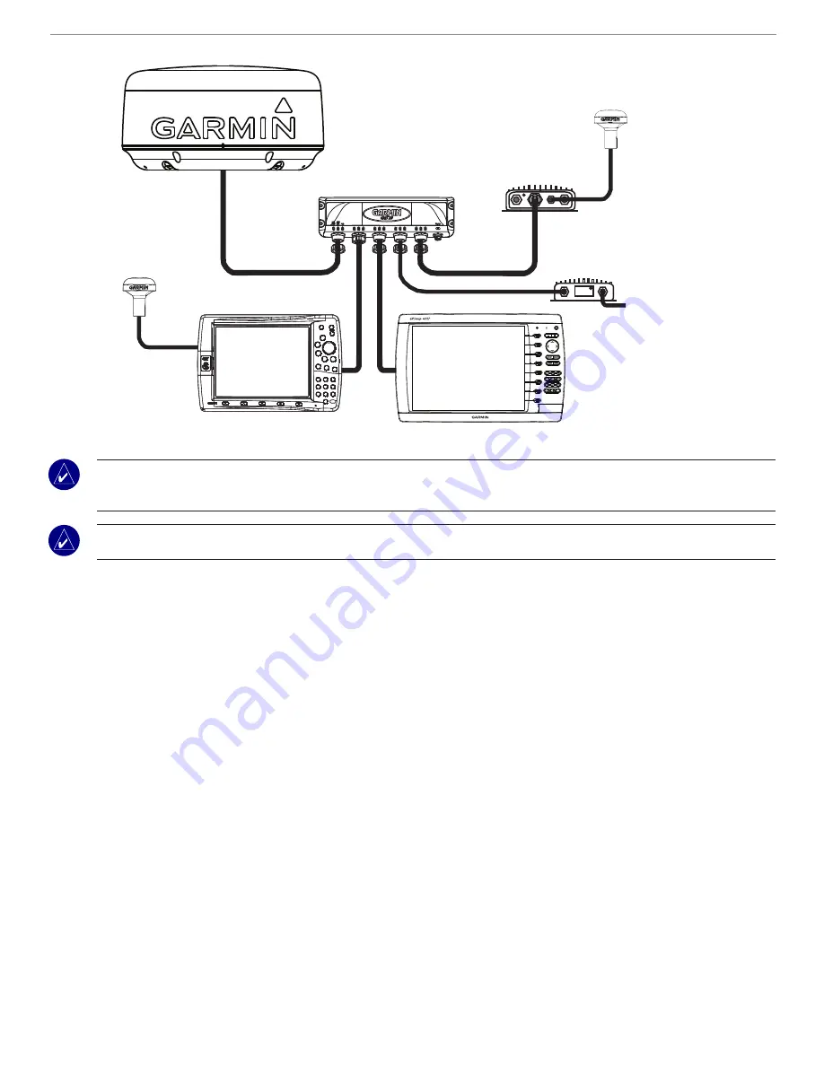
Expanded Network

Garmin GMS 10 marine network 

port expander

Garmin GDL 0/0A marine 

weather/audio satellite 

receiver

GA 1

GSD 22 sounder module

to transducer

Garmin 

Chartplotter

Garmin 

Chartplotter

GMR 18/24 marine radar

GPS 17


Note: 

When using the GMR 18/24 with an expanded network, each network component must be installed according to its installation 

instructions. This diagram only shows how a GMR 18/24 radar communicates with an expanded network, and does not show the full wiring needs 

of the other network components.


Note: 

The GMR 18/24, Garmin chartplotter, and the other network components must be connected to a power source according to their 

installation instructions. This diagram only illustrates the network data connections.

Front of Boat Offset

Depending on the scanner installation, it may be necessary to adjust the Front of Boat Offset. If the scanner installation requires a 180° offset, 

change the Front of Boat Offset to 180° and test the radar. If the Front of Boat Offset needs further adjustment, continue with the procedure below.
Using the bow of the ship, take an optical bearing of a stationary target located within viewable range. Measure the target bearing on the radar. 

If the bearing deviation is more than +/- 1°, then do the following to access the Front of Boat Offset from the menu on your chartplotter:

Front of Boat Offest on a 3000 Series chartplotter:

1. From the Radar Page, press the 

ADJ

 key to display the Adjustment Menu.

2. From the Adjustment Menu, select 

Setup,

 and press 

ENTER

. Using the 

Rocker

, select the 

Advanced

 tab.

3. Using the 

ROCKER

, highlight the 

Front of Boat Offset

 slider, and press 

ENTER

.

4. Adjust the Front of Boat Offset.

Front of Boat Offset on a 4000/5000 Series chartplotter:

1. From the Home screen, select 

Radar 

Radar Setup 

Advanced 

>

 Front Of Boat

.

2. Adjust the Front of Boat Offset.

Using the Radar

All functions of the GMR 18/24 radar are controlled using your Garmin marine network chartplotter. See the Radar section of your 

chartplotter's manual for operating instructions. If your chartplotter's manual does not contain a Radar section, download the latest revision of 

the manual from 

http://www.garmin.com/support/userManual.jsp

Summary of Contents for GMR 18

Page 1: ...GMR 18 24 marine radar installation instructions ...

Page 2: ...lectronic storage medium to be viewed and to print one copy of this manual or of any revision hereto provided that such electronic or printed copy of this manual must contain the complete text of this copyright notice and provided further that any unauthorized commercial distribution of this manual or any revision hereto is strictly prohibited Information in this document is subject to change with...

Page 3: ...Support by phone 913 397 8200 or 800 800 1020 Monday Friday 8 AM 5 PM Central Time or go to www garmin com support In Europe contact Garmin Europe Ltd at 44 0 870 8501241 outside the UK or 0808 2380000 within the UK Note The Garmin GMR 18 24 has no user serviceable parts If you encounter a problem with your unit please take it to an authorized Garmin NMEA dealer or contact Garmin Product Support f...

Page 4: ...ounted out of range of personnel horizontal beam width above head height When the scanner is transmitting do not look directly at the antenna at close range eyes are the most sensitive part of the body to electromagnetic energy When properly installed and operated the use of this radar conforms to the requirements of ANSI IEEE C95 1 1992 Standard for Safety Levels with Respect to Human Exposure to...

Page 5: ...ng or twisting of the cables See the following Cable Runs section for more information 4 Position the scanner on the mounting surface with the triangular mark on the case aligned to the front of the vessel Apply a bead of marine sealant around each of the mounting holes on the mounting surface 5 Install the four 4 M8 x 1 25 x 60 threaded rods into the Mounting Holes on the bottom of the scanner Th...

Page 6: ...ire gauge table on the previous page when using extended runs of wire between the power cable and the battery Final Wiring Connections Making the final wiring connections 1 Connect the Black ground wire to the vessel s negative power terminal 2 Connect the Red power wire with fuse holder to the vessel s positive power terminal Warning Do not cut the fuse holder from the red wire The fuse holder mu...

Page 7: ...adar If the Front of Boat Offset needs further adjustment continue with the procedure below Using the bow of the ship take an optical bearing of a stationary target located within viewable range Measure the target bearing on the radar If the bearing deviation is more than 1 then do the following to access the Front of Boat Offset from the menu on your chartplotter Front of Boat Offest on a 3000 Se...

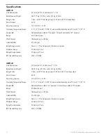
Page 8: ... scale whichever is greater Minimum Range 20 meters 65 feet Range Discrimination 20 meters 65 feet RF Transmit Frequency 9410 30 MHz GMR 24 Unit Dimensions 610 mm 24 D x 248 9 mm 9 13 16 H Radar Scanner Weight Unit 9 12 kg 20 1 lbs cable 3 81 kg 8 4 lbs Range Scales 1 8 nm with 1 32 nm range rings to 48 nm with 12 nm range rings Power Output 4 kW Power Input Source 10 5 35 VDC 33 5 W Operating Tem...

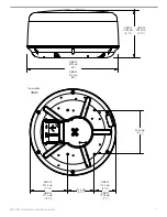
Page 9: ...n Instructions Towards Bow GMR 18 236 4 mm 9 5 16 GMR 24 248 9 mm 9 13 16 GMR 18 457 0 mm 18 GMR 24 610 mm 24 233 0 mm 9 5 32 141 5 mm 5 9 16 GMR 18 201 5 mm 7 15 16 GMR 24 277 4 mm 10 29 32 GMR 18 114 0 mm 4 15 32 GMR 24 190 8 mm 7 1 2 ...

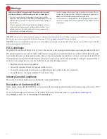
Page 10: ...at to which the receiver is connected Consult the dealer or an experienced radio TV technician for help Industry Canada Compliance The Garmin 18 24 Marine Radar complies with Industry Canada Standard RSS 138 Declaration of Conformity DoC Hereby Garmin declares that this GMR 18 24 is in compliance with the essential requirements and other relevant provisions of Directive 1999 5 EC To view the full ...

Page 11: ...TE IN NO EVENT SHALL GARMIN BE LIABLE FOR ANY INCIDENTAL SPECIAL INDIRECT OR CONSEQUENTIAL DAMAGES WHETHER RESULTING FROM THE USE MISUSE OR INABILITY TO USE THIS PRODUCT OR FROM DEFECTS IN THE PRODUCT Some states do not allow the exclusion of incidental or consequential damages so the above limitations may not apply to you Garmin retains the exclusive right to repair or replace the unit or softwar...

Page 12: ...t www garmin com 2007 Garmin Ltd or its subsidiaries Garmin International Inc 1200 East 151st Street Olathe Kansas 66062 USA Garmin Europe Ltd Liberty House Hounsdown Business Park Southampton Hampshire SO40 9RB UK Garmin Corporation No 68 Jangshu 2nd Road Shijr Taipei County Taiwan www garmin com Part Number 190 00831 02 Rev B ...

Reviews: