background image

PRELIMINARY

PRELIMINARY

GMR 404/406 Owner’s Manual 

 i

I

NTRODUCTION

About This Manual

Thank you for choosing Garmin’s GMR 404/406 marine radar. The 

addition of the GMR 404/406 marine radar to your Garmin Marine 

Network, enhances the capability of your system by adding graphical 

radar data to your Garmin chartplotter.
This manual covers the features and operation of the GMR 404/406 

marine radar when viewed on the Garmin chartplotters. To get the 

most out of your new radar, take time to read this manual and learn 

the operating procedures for your unit in detail.
The Introduction contains information about this manual and the 

Table of Contents.
The Main Pages contain information on the setup and operation of the 

GMR 404/406. 
The Appendix contains information such as specifi cations and license 

requirements. You can also fi nd warranty and FCC information in the 

Appendix. 
Use the Index as a key word search to help you fi nd information more 

quickly.

 Terminology Used Throughout This Manual

•   This manual refers to the radome hardware as the “scanner,” 

“radar,” or “GMR 404/406.” These terms can be used 

interchangeably.

•   This manual uses the term “chartplotter” when referring to a 

Garmin GPSMAP 3000 series multi-function display.

•   This manual uses the term “Radar Page.” The Radar Page is 

a dedicated page on the Garmin chartplotter showing radar 

information. Radar information can be displayed as a split 

screen on any of the chartplotter main pages.     

•   This manual uses the term “ highlight” when referring to the 

on-screen cursor. To highlight something, use the Rocker key 

on the chartplotter to move  the cursor to the desired item. The 

on-screen cursor is represented by a highlighted yellow box.

I

NTRODUCTION

 > 

A

BOUT

 T

HIS

 M

ANUAL


Prelimimary Copy—For Review Only

GMR 404_406 Owners Manual Preliminary Review.indd   1

3/27/2006   4:08:12 PM

Summary of Contents for GMR 406

Page 1: ...PRELIMINARY PRELIMINARY Owner s Manual marine radar GMR 404 406 GMR 404_406 Owners Manual Preliminary Review indd 1 3 27 2006 4 08 12 PM...

Page 2: ...s manual or of any revision hereto provided that such electronic or printed copy of this manual must contain the complete text of this copyright notice and provided further that any unauthorized comme...

Page 3: ...nts You can also nd warranty and FCC information in the Appendix Use the Index as a key word search to help you nd information more quickly Terminology Used Throughout This Manual This manual refers t...

Page 4: ...t Time Constant 7 Zoom 8 Target Expansion 8 Trails 9 Guard Zone 9 VRM EBL 10 MARPA 11 MARPA Setup 12 Hide Show Navigation Features 13 Additional Adjustment Menu Items 13 Map Cursor On Off 14 Setup 14...

Page 5: ...update may be needed for the GMR 404 406 to function properly If the message Incompatible Software Version is displayed when the chartplotter is powered on the software in the chartplotter needs to be...

Page 6: ...adar transmits microwave energy that has the potential to be harmful to humans and animals Before beginning radar transmission verify that the area around the scanner is clear The GMR 404 406 transmit...

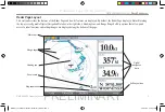
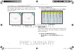
Page 7: ...a Heading Line and Range Rings Soft key options that allow quick access to radar functions and setting changes are displayed along the bottom of the page Status bar Range rings Zoom scale Ring separa...

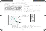
Page 8: ...rks can help in quickly determining the azimuth to a target The lower scale represents the distance between the Range Rings Heading Line The Heading Line is shown from your current position along the...

Page 9: ...dar Page There are several adjustment options available Gain Sea Clutter Rain Clutter FTC Zoom Target Expansion Trails Guard Zone VRM EBL MARPA and Hide Show Navigation Features All adjustments are ma...

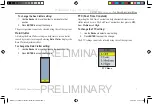
Page 10: ...e Manually adjusting the gain increases or decreases the receiver s sensitivity Increasing the gain may help to show a distant target but may also increase screen clutter To change the Gain setting 1...

Page 11: ...t slider To change the Rain Clutter setting 1 Use the Rocker to move the slider to the desired setting 2 Press ENTER to accept the change FTC Fast Time Constant Adjusting the Fast Time Constant can he...

Page 12: ...he selection box 1 Use the Rocker to move the pointer and highlight the edge of the selection box 2 Press ENTER to activate the Move function 3 Use the Rocker to move the selection box to a new locati...

Page 13: ...ge Trails Off Trails On medium To clear the Trails select Clear Trails on the Adjustment Menu or press the Clear Trails soft key Guard Zone A Guard Zone is a user de ned area of protection If a target...

Page 14: ...ne target to another Two V E tools can be active at the same time The VRM EBL Menu has two areas VRM EBL 1 and VRM EBL 2 Each area has two settings Show Hide and Adjust To activate VRM EBL 1 or 2 Use...

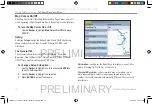
Page 15: ...ires the use of a heading sensor The heading sensor must output the NMEA sentence HDM or HDG at format 0183 v2 30 or higher The Gamin Marine Network has been tested using the KVH 1000 heading sensor u...

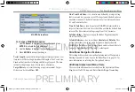
Page 16: ...rget To display the MARPA List Use the Rocker to highlight MARPA List and press ENTER MARPA List MARPA Setup The MARPA Setup Menu contains settings for Vector Length Target History Own Vessel Safe Zon...

Page 17: ...miles Time To Safe Zone sounds an alarm if MARPA determines that a target will intersect the Own Vessel Safe Zone within the de ned time interval The time interval settings range from 3 to 24 minutes...

Page 18: ...entation Cross talk Rejection Front of Boat Offset Timed Transmit Timed Transmit XMIT Time and Timed Transmit STBY Time To change a Setup eld option 1 Use the Rocker to highlight the eld and press ENT...

Page 19: ...ands by for a period of ten minutes before referring to the Timed Transmit XMIT Time When the radar is standing by the scanner does not rotate or transmit however power is still applied to the Magnetr...

Page 20: ...ne and Course Line When selected that feature is displayed on the Radar Page Waypoints displays user waypoints on the Radar Page Bearing Line displays a bearing line on the Radar Page The bearing line...

Page 21: ...mode and after Spinning Up the scanner begins transmitting To select Enter Standby or Begin Transmitting Use the Rocker to highlight the Enter Standby or Begin Transmitting and press ENTER Map Page R...

Page 22: ...e These options do affect operation of the radar and the Radar Page To display the Radar Options 1 Press ADJ MENU 2 Use the Rocker to highlight Radar Options and press ENTER GMR 404 406 OPERATION MAP...

Page 23: ...m I Hungary Cyprus G Ireland Malta Italy G Iceland G Latvia I Norway I Lithuania G Switzerland I I Requires an individual license for operation G can be operated under a general license or license exe...

Page 24: ...amwidth of 3 6 nominal vertical beamwidth of 25 nominal Range GMR 404 24 nm GMR 406 36 nm Wind Velocity Wind speed up to 100 Kts Antenna RPMs 24 rpm Range Ring Accuracy 1 meter Bearing Accuracy 1 Mini...

Page 25: ...ed to try to correct the interference by one of the following measures Reorient or relocate the receiving antenna Increase the separation between the equipment and the receiver Connect the equipment i...

Page 26: ...are to any country in violation of the export control laws of the United States of America LIMITED WARRANTY This Garmin product is warranted to be free from defects in materials or workmanship for one...

Page 27: ...gh online auctions are not eligible for rebates or other special offers from Garmin Online auction con rmations are not accepted for warranty veri cation To obtain warranty service an original or copy...

Page 28: ...ur Web site at http www garmin com prop65 Warning Failure to avoid the following potentially hazardous situations may result in injury or property damage Use the GMR 404 406 at your own risk To reduce...

Page 29: ...ap Cursor 13 Map Cursor On Off 14 Map Page Radar Overlay 17 MARPA 5 11 MARPA function 11 MARPA List 12 MARPA Setup 12 MARPA Setup Menu 12 MARPA Tab 16 MARPA target 11 Mini Automatic Radar Plotting Aid...

Page 30: ...nge Marker 10 Vector Length 13 Velocity Reference 13 VRM EBL 5 10 W Warming Up 2 Warning and Cautions 24 WARRANTY 22 Waypoints 16 Z Zoom 5 8 Zoom level 8 Zoom Scale 3 Prelimimary Copy For Review Only...

Page 31: ...PRELIMINARY PRELIMINARY Prelimimary Copy For Review Only GMR 404_406 Owners Manual Preliminary Review indd 27 3 27 2006 4 08 24 PM...

Page 32: ...s subsidiaries Garmin International Inc 1200 East 151st Street Olathe Kansas 66062 U S A Garmin Europe Ltd Unit 5 The Quadrangle Abbey Park Industrial Estate Romsey SO51 9DL U K Garmin Corporation No...

Reviews: