Page 1-6
G300 Installation Manual –Installation Overview
Revision A
190-00921-01
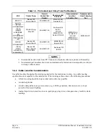
Table 1-5. Pin Contact and Crimp Tools Part Numbers
LRU Contact
Type
Garmin
Contact Part
Number
Recommended
Positioner
Recommended
Insertion/
Extraction Tool
Recommended
Hand Crimping
Tool
GDU 37X
Socket, Mil
Crimp, Size 20
336-00094-00
M22520/2-08,
Daniels K13-1
GSU 73
GTP 59
011-00979-20
(Config
module
w/EEPROM
kit)
011-00981-00
(thermocouple
kit)
Pin, Mil Crimp,
Size 22D
336-00021-00
Positronic P/N
9502-4,
ITT P/N
M22520/2-09,
Daniels P/N K42
GMU 44
Socket, Mil
Crimp, Size 20
336-00022-00
M22520/2-08,
Daniels K13-1
011-00979-22
(Config
module
w/Sockets &
Jackscrew kit)
Socket, Mil
Crimp, Size 20,
26-30 AWG
336-00022-01
Positronic P/N
9502-5
M81969/1-04
for size 22D
pins and
M81969/1-02
for size 20 pins
M22520/2-01
NOTES
1.
Insertion/Extraction tools from ITT Cannon are all plastic; others are plastic with metal tip.
2.
Non-Garmin part numbers shown are not maintained by Garmin and consequently are subject
to change without notice.
1.6.2
Cable Location Considerations
Use cable meeting the applicable aviation regulation for the interconnect wiring. Any cable meeting
specifications is acceptable for the installation. When routing cables, observe the following precautions:
•
All cable routing should be kept as short and as direct as possible.
•
Avoid
sharp
bends.
•
Avoid routing cables near power sources (e.g., 400 Hz generators, trim motors, etc.) or near
power for fluorescent lighting.
•
Analog Input wires routed too close to spark plugs, plug wires, or magnetos may result in erratic
readings.

