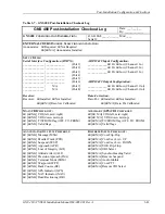
Post-Installation Configuration & Checkout
GNS 480 (CNX80) Installation Manual560-0982-01 Rev A
3-41
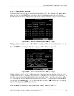
1.
Press the
MAP
bezel key and use the large, outer knob to select MAP 2.
2.
Press the
MENU/ENTER
key to display the line select key functions, and repeatedly press the
MORE
line select key until the
NAV DATA
line select key legend is displayed.
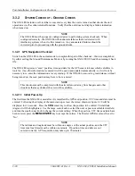
3.
Press the
NAV DATA
line select key to display nav data in the window on the left.
4.
Press the
SEL DATA
line select key and use the small, inner knob to select the CO LVL field for
display and press
MENU/ENTER
when the appropriate field is selected. Verify that this carbon
monoxide level value is not dashed out, and that the level agrees with the detector.
3.3.3 S
YSTEM
C
HECKOUT
–
F
LIGHT
C
HECKS
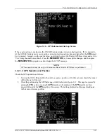
All system functions that cannot be adequately tested on the ground will require a flight test. Even if all
functions can be verified on the ground, a flight test is recommended as a final installation verification.
Verify system operation as described in the following sections.
3.3.3.1 Com Flight Test Check
1.
Verify the com performance by contacting a ground station at a range of at least 50nm while
maintaining an appropriate altitude, and over all normal flight attitudes. Performance should be
checked using low, high, and mid band frequencies.
3.3.3.2 VOR Flight Test Check
1.
Tune a local VOR station within 50 miles.
2.
Verify the audio ident/voice quality.
3.
Verify the Morse code decoder IDs the station (95% probability).
4.
Fly to and from the station.
5.
Verify NAV flag, TO/FROM flag, and CDI are operational.
6.
Record accuracy in System Log (see manual).
3.3.3.3 ILS Flight Test Check
1.
Tune an ILS at the local airport.
2.
Verify the audio ident/voice quality.
3.
Verify the Morse code decoder IDs the station (95% probability).
4.
Fly the approach.
5.
Verify NAV flag, GS flag, and CDI and VDI are operational.
6.
Verify BC annunciator.
3.3.3.4 GPS Flight Test Check
1.
Verify that GPS position is not lost during normal aircraft maneuvering (e.g. bank angles of up to 30
degrees and pitch angles associated with take-off, departures, approaches, landing and missed
approaches as applicable). If GPS position is lost, a “
WARNING Loss of Navigation
” message
will be displayed.
2.
Enter and activate a flight plan on the GNS 480. Fly the flight plan and verify that the display of
flight plan data is consistent with the CDI indication (deviation, TO/FROM…) in the pilot’s primary
field of view.
Summary of Contents for GNS 480
Page 1: ...GNS 480 CNX80 Color GPS Nav Com Installation Manual September 2004 560 0982 01 Rev A...
Page 10: ...Table of Contents viii 560 0982 01 Rev A GNS 480 CNX80 Installation Manual NOTES...
Page 30: ...General Information 1 20 560 0982 01 Rev A GNS 480 CNX80 Installation Manual NOTES...
Page 126: ...Periodic Maintenance 6 2 560 0982 01 Rev A GNS 480 CNX80 Installation Manual NOTES...
Page 150: ...Appendix D Interconnect Diagrams D 2 560 0982 01 Rev A GNS 480 CNX80 Installation Manual NOTES...
Page 185: ......
Page 186: ......

