Installation Procedures
2-2
560-0982-01 Rev A
GNS 480 (CNX80) Installation Manual
2.3.2 O
PTIONAL
A
CCESSORIES
N
OT
S
UPPLIED
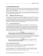
For a list of optional accessories that are available but not supplied with the GNS 480, refer to Appendix F.
2.4 S
PECIAL
T
OOLS
R
EQUIRED
Some of the connectors use crimp contacts. The tables below identify crimp tools required to ensure
consistent, reliable crimp contact connections for the rear D-sub connectors. The tables define one source
for the crimp tool. Alternate equivalent tools may be used.
Table 2-1 - Crimp Tool for P/N 162-0082
Description
ITT/Cannon P/N Military number
Insertion/Extraction tool CIET-22D
271-7048-000
M81969/14-01
Crimp tool
995-0001-584
M22520/2-01
Positioner N/A
M22520/2-09
Table 2-2 - Crimp Tool for P/N 245-0027
Description
ITT/Cannon P/N Military number
Insertion/Extraction tool CIET-20HD 980-200-426
M81969/39-01
Crimp tool
995-0001-584
M22520/2-01
Positioner 995-0001-604
M22520/2-08
Below is the contact for ITT/Cannon crimp tools:
ITT Cannon
Phone (714) 557-4700 or 1-800-854-3028
666 E. Dyer Road
FAX (714) 628-2142
Santa Ana, CA 92705-5612
2.5 I
NSTALLATION
C
ONSIDERATIONS
Installation of this STC does not change the types of approved airplane operations as defined by FAR
23.1525 (e.g. IFR, VFR, day or night). If a change in approved operations is desired, additional aircraft
approvals or inspections will be required.
2.5.1 M
INIMUM
S
YSTEM
C
ONFIGURATION
2.5.1.1 VFR Installation
The minimum GNS 480 installation requires the following items for a VFR Installation:
•
GNS 480 GPS/WAAS/Nav/Com (installed in the aircraft manufacturer approved location)
•
GPS antenna, Nav antenna and Com antenna.
•
To take full advantage of the GNS 480 capabilities an optional altitude source is recommended for
automatic sequencing of course-to-altitude (CA) and heading-to-altitude (VA) leg types. If no
altitude data is provided to the GNS 480, CA and VA legs must be manually sequenced.
Without an external CDI, no glideslope information is obtainable. However, the unit will maintain full
VOR and Localizer functionality including an internal CDI display.
The installation must be placarded “GPS LIMITED TO VFR USE ONLY” in clear view of the pilot.
2.5.1.2 IFR VOR/LOC/GS Installation
The minimum GNS 480 installation requires the following items for an IFR VOR/LOC/GS Installation:
•
GNS 480 GPS/WAAS/Nav/Com (installed in the aircraft manufacturer approved location)
Summary of Contents for GNS 480
Page 1: ...GNS 480 CNX80 Color GPS Nav Com Installation Manual September 2004 560 0982 01 Rev A...
Page 10: ...Table of Contents viii 560 0982 01 Rev A GNS 480 CNX80 Installation Manual NOTES...
Page 30: ...General Information 1 20 560 0982 01 Rev A GNS 480 CNX80 Installation Manual NOTES...
Page 126: ...Periodic Maintenance 6 2 560 0982 01 Rev A GNS 480 CNX80 Installation Manual NOTES...
Page 150: ...Appendix D Interconnect Diagrams D 2 560 0982 01 Rev A GNS 480 CNX80 Installation Manual NOTES...
Page 185: ......
Page 186: ......


