


500W Series Installation Manual
Page 1-7
190-00357-02
Rev. D
1.4.5
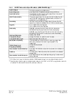
VOR Specifications (GNS 530W Only)
Receiver Audio Sensitivity
At -103.5 dBm (S+N)/N is not less than 6 dB.
Course Deviation Sensitivity
-103.5 dBm or less for 60% of standard deflection.
Flag
The VOR Course Deviation Flag must be flagged:
a) in the absence of an RF signal.
b) in the absence of the 9960 Hz modulation.
c) in the absence of either one of the two 30 Hz modulations.
d) When the level of a standard VOR deviation test signal
produces less than a 50% of standard deflection.
AGC Characteristics
From -99 dBm to -13 dBm input of a Standard VOR Audio Test
Signal, audio output level does not vary more than 3 dB.
Spurious Response
Greater than 80 dB.
VOR OBS Bearing Accuracy
The bearing information as presented to the pilot does not have an
error in excess of 2.7° as specified by RTCA DO-196 and EuroCAE
ED-22B.
Audio Output
A minimum 100 mW into a 500
Ω
load.
Audio Response
Less than 6 dB of variation between 350 and 2500 Hz. Except the
1020 Hz Ident Tone is at least 20 dB down in voice mode.
Audio Distortion
The distortion in the receiver audio output does not exceed 10% at
all levels up to 100 mW.
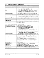
1.4.6
LOC Specifications (GNS 530W Only)
Receiver Audio Sensitivity
At -103.5 dBm (S+N)/N is not less than 6 dB.
Course Deviation Sensitivity
-103.5 dBm or less for 60% of standard deflection.
Flag
The LOC Course Deviation Flag must be flagged:
a) In the absence of an RF signal.
b) When either the 90 or 150 Hz modulating signals is removed
and the other is maintained at its normal 20%.
c) In the absence of both 90 and 150 Hz modulation.
d) When the level of a standard localizer deviation test signal
produces less than a 50% of standard deflection.
AGC Characteristics
From -86 dBm and -33 dBm input of a Standard VOR Audio Test
Signal, audio output level does not vary more than 3 dB.
Selectivity
Nose Bandwidth: The input signal level required to produce the
reference AGC voltage does not vary more than 6 dB over the
input signal frequency range of ± 9 kHz from the assigned channel
frequency.
Skirt Bandwidth: The input signal level required to produce
reference AGC voltage is at least 70 dB greater than the level
required to produce reference AGC voltage at the assigned
channel frequency at ± 36 kHz from the assigned channel
frequency.
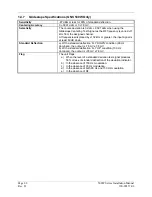
Spurious Response
Greater than 80 dB.
Centering Accuracy
Typical 0
±
3 mV (Max error 9.9 mV per RTCA DO-195).
Audio Output
A minimum 100 mW into a 500
Ω
load.
Audio Response
Less than 6 dB of Variation between 350 and 2500 Hz. Except the
1020 Hz Ident Tone is at least 20 dB down in voice mode.
Audio Distortion
The distortion in the receiver audio output does not exceed 10% at
all levels up to 100 mW.
Summary of Contents for GNS 530W
Page 2: ...500W Series Installation Manual 190 00357 02 Rev D...
Page 130: ...Page 7 4 500W Series Installation Manual Rev D 190 00357 02 This Page Intentionally Left Blank...
Page 132: ...Page 8 2 500W Series Installation Manual Rev D 190 00357 02 This Page Intentionally Left Blank...
Page 134: ...Page A 2 500W Series Installation Manual Rev D 190 00357 02 This Page Intentionally Left Blank...
Page 136: ...Page B 2 500W Series Installation Manual Rev D 190 00357 02 This Page Intentionally Left Blank...
Page 137: ...500W Series Installation Manual Page C 1 190 00357 02 Rev D Appendix C RESERVED...
Page 138: ...Page C 2 500W Series Installation Manual Rev D 190 00357 02 This Page Intentionally Left Blank...
Page 148: ...Page E 6 500W Series Installation Manual Rev D 190 00357 02 This Page Intentionally Left Blank...
Page 150: ...Page F 2 500W Series Installation Manual Rev D 190 00357 02 This Page Intentionally Left Blank...
Page 160: ...Page G 6 500W Series Installation Manual Rev D 190 00357 02 This Page Intentionally Left Blank...
Page 162: ...Page H 2 500W Series Installation Manual Rev D 190 00357 02 This Page Intentionally Left Blank...
Page 188: ...Page H 28 500W Series Installation Manual Rev D 190 00357 02 Figure H 16 GTX 330 Interconnect...
Page 194: ...Page H 34 500W Series Installation Manual Rev D 190 00357 02 Figure H 20 RMI OBI Interconnect...
Page 198: ...Page H 38 500W Series Installation Manual Rev D 190 00357 02 Figure H 24 TAWS Interconnect...
Page 211: ...500W Series Installation Manual Page H 51 190 00357 02 Rev D Figure H 33 Switches Interconnect...
Page 215: ......
Page 216: ......


