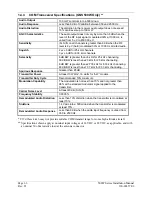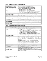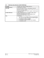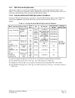
Page 2-4
500W Series Installation Manual
Rev. D
190-00357-02
1.
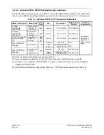
Mount the antenna as close to level as possible with respect to the normal cruise flight
attitude of the aircraft. If the normal flight attitude is not known, substitute the waterline,
which is typically referenced as level while performing a weight and balance check.
2.
The GPS antenna should be mounted in a location to minimize the effects of airframe
shadowing during typical maneuvers. Typically mounting farther away from the tail
section reduces signal blockage seen by the GPS antenna.
3a.
The GPS antenna should be mounted no closer than two feet from any VHF COM antenna
or any other antenna which may emit harmonic interference at the L1 frequency of 1575.42
MHz. An aircraft EMC check (reference VHF COM interference check in Post Installation
Checkout procedures) can verify the degradation of GPS in the presence of interference
signals. If an EMC check reveals unacceptable interference, insert a GPS notch filter in
line with the offending VHF COM or the (re-radiating) ELT transmitter.
Note: When mounting a combination antenna (ex. GPS and COM, GPS and XM), the
recommended distance of two feet or more is not applicable to the distance between the
antenna elements provided the combination antenna is TSO authorized and has been tested
to meet Garmin’s minimum performance standards.
3b.
The GPS antenna should be mounted no closer than two feet from any antennas emitting
more than 25 watts of power. An aircraft EMC check can verify the degradation of GPS in
the presence of interference signals.
3c.
To minimize the effects of shadowing at 5
°
elevation angles, the GPS antenna should be
mounted no closer than 6 inches (edge to edge) from other antennas, including passive
antennas such as another GPS antenna or XM antenna.
4.
To maintain a constant gain pattern and limit degradation by the windscreen, avoid
mounting the antenna closer than 3 inches from the windscreen.
5.
For multiple GPS installations, the antennas should not be mounted in a straight line from
the front to the rear of the fuselage. Also varying the mounting location will help
minimize any aircraft shading by the wings or tail section (in a particular azimuth, when
one antenna is blocked the other antenna may have a clear view).
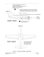
Figure 2-1 shows the recommended placement of antennas.
2.4.2
COM Antenna Location
The GNS 530W COM antenna should be well removed from all projections, engines and propellers. The
ground plane surface directly below the antenna should be a flat plane over as large an area as possible
(18 inches square, minimum). The antenna should be mounted a minimum of six feet from any DME or
other COM antennas, four feet from any ADF sense antennas, and two feet from the 500W Series unit
and its GPS antenna. The COM antenna should also be mounted as far apart as practical from the ELT
antenna. Some ELTs have exhibited re-radiation problems generating harmonics that may interfere with
GPS signals. This can happen when the COM (500W Series unit or any other COM) is transmitting on
certain frequencies such as 121.15 or 121.175 MHz, which may cause the ELT output circuit to oscillate
from the signal coming in on the ELT antenna coax.
If simultaneous use of two COM transceivers is desired (split-COM or simul-comm), use of the TX
interlock function is mandatory. In addition, the COM antennas should be spaced for maximum
isolation. A configuration of one topside antenna and one bottom side antenna is recommended.
Summary of Contents for GNS 530W
Page 2: ...500W Series Installation Manual 190 00357 02 Rev D...
Page 130: ...Page 7 4 500W Series Installation Manual Rev D 190 00357 02 This Page Intentionally Left Blank...
Page 132: ...Page 8 2 500W Series Installation Manual Rev D 190 00357 02 This Page Intentionally Left Blank...
Page 134: ...Page A 2 500W Series Installation Manual Rev D 190 00357 02 This Page Intentionally Left Blank...
Page 136: ...Page B 2 500W Series Installation Manual Rev D 190 00357 02 This Page Intentionally Left Blank...
Page 137: ...500W Series Installation Manual Page C 1 190 00357 02 Rev D Appendix C RESERVED...
Page 138: ...Page C 2 500W Series Installation Manual Rev D 190 00357 02 This Page Intentionally Left Blank...
Page 148: ...Page E 6 500W Series Installation Manual Rev D 190 00357 02 This Page Intentionally Left Blank...
Page 150: ...Page F 2 500W Series Installation Manual Rev D 190 00357 02 This Page Intentionally Left Blank...
Page 160: ...Page G 6 500W Series Installation Manual Rev D 190 00357 02 This Page Intentionally Left Blank...
Page 162: ...Page H 2 500W Series Installation Manual Rev D 190 00357 02 This Page Intentionally Left Blank...
Page 188: ...Page H 28 500W Series Installation Manual Rev D 190 00357 02 Figure H 16 GTX 330 Interconnect...
Page 194: ...Page H 34 500W Series Installation Manual Rev D 190 00357 02 Figure H 20 RMI OBI Interconnect...
Page 198: ...Page H 38 500W Series Installation Manual Rev D 190 00357 02 Figure H 24 TAWS Interconnect...
Page 211: ...500W Series Installation Manual Page H 51 190 00357 02 Rev D Figure H 33 Switches Interconnect...
Page 215: ......
Page 216: ......

