500W Series Installation Manual
Page 2-9
190-00357-02
Rev. D
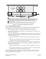
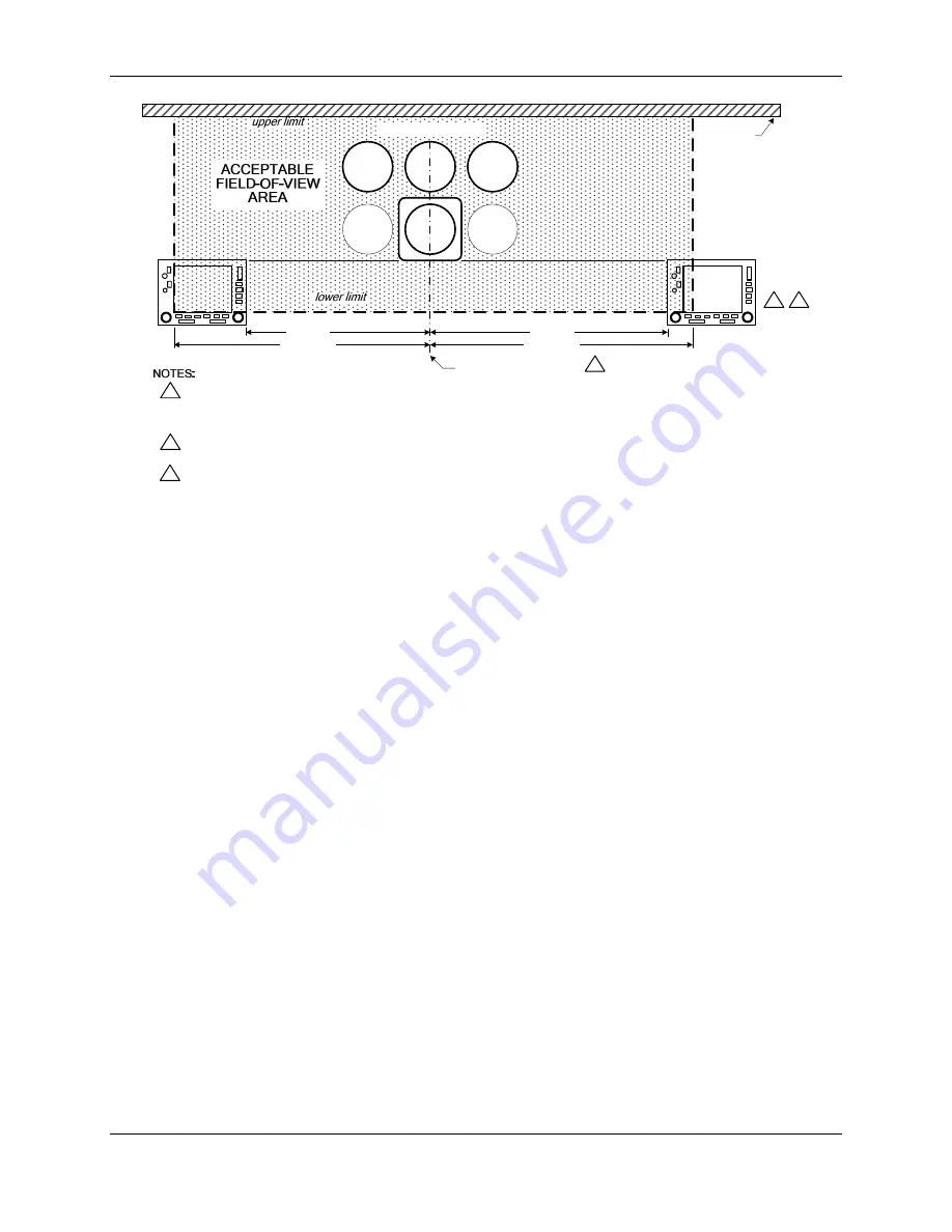
Pilot's Instrument 'T'
Instrument 'T' Centerline
13.856 in
13.856 in
Glareshield
1
1. FOR AIRCRAFT WITHOUT THE BASIC INSTRUMENT 'T' CONFIGURATION, THE CENTER OF THE PILOT'S YOKE
OR CONTROL STICK IN THE NEUTRAL POSITION SHOULD BE USED TO DETERMINE THE CENTERLINE. IF THE
CONTROL YOKE/STICK IS OFFSET FROM THE CENTER OF THE PILOT’S SEAT, AN IMAGINARY LINE EXTENDED
THROUGH THE CENTER OF THE PILOT’S SEAT MAY BE USED AS THE PRIMARY VIEW CENTERLINE.
2. THE TOP EDGE OF THE 500W SERIES SHOULD BE NO LOWER THAN THE BOTTOM EDGE OF THE PRIMARY
FLIGHT INSTRUMENTS.
3. FOR AIRCRAFT IN WHICH THE TYPE CERTIFICATED CDI OR HSI LOCATION IS BELOW THE BASIC 'T', THE
LOWER LIMIT OF THE ACCEPTABLE FIELD-OF-VIEW SHOULD BE THE BOTTOM OF THE CDI OR HSI.
2
3
12.1 in
8.8 in
Figure 2-2. Source Selection Annunciation Field of View
2.5.1.2 GPS Navigation Annunciation
Use the steps below to determine whether or not the integrated GPS navigation annunciation displayed
on the 500W Series unit to be installed is within the acceptable field-of-view (see Figure 2-3):
1.
Determine the pilot’s primary view centerline, as defined in Step 1 of Section 2.5.1.1.
2.
Measure the horizontal distance from the primary view centerline to the left or right edge of the
500W Series, as appropriate.
3.
If the 500W Series unit is mounted to the right of the primary instruments, the internal display of
annunciation within the 500W Series unit is considered to be within the acceptable field-of-view
if the following criteria are met:
•
The left edge of the 500W Series unit is within 13.8 inches of the primary view centerline
and;
•
the top edge of the 500W Series unit is no lower than the bottom edge of the primary flight
instruments or the unit is line abreast with the affected CDI.
4.
If the 500W Series unit is mounted to the left of the primary instruments, the internal display of
annunciation within the 500W Series unit is considered to be within the acceptable field-of-view
if the following criteria are met:
•
The right edge of the 500W Series unit is within 11.8 inches of the primary view center line
and;
•
the top edge of the 500W Series unit is no lower than the bottom edge of the primary flight
instruments or the unit is line abreast with the affected CDI.
If the internal display of GPS navigation annunciation within the 500W Series unit does not meet the
criteria for acceptable field-of-view as defined above, an external annunciator unit must be installed
within 16.805 inches of the view centerline.
Summary of Contents for GNS 530W
Page 2: ...500W Series Installation Manual 190 00357 02 Rev D...
Page 130: ...Page 7 4 500W Series Installation Manual Rev D 190 00357 02 This Page Intentionally Left Blank...
Page 132: ...Page 8 2 500W Series Installation Manual Rev D 190 00357 02 This Page Intentionally Left Blank...
Page 134: ...Page A 2 500W Series Installation Manual Rev D 190 00357 02 This Page Intentionally Left Blank...
Page 136: ...Page B 2 500W Series Installation Manual Rev D 190 00357 02 This Page Intentionally Left Blank...
Page 137: ...500W Series Installation Manual Page C 1 190 00357 02 Rev D Appendix C RESERVED...
Page 138: ...Page C 2 500W Series Installation Manual Rev D 190 00357 02 This Page Intentionally Left Blank...
Page 148: ...Page E 6 500W Series Installation Manual Rev D 190 00357 02 This Page Intentionally Left Blank...
Page 150: ...Page F 2 500W Series Installation Manual Rev D 190 00357 02 This Page Intentionally Left Blank...
Page 160: ...Page G 6 500W Series Installation Manual Rev D 190 00357 02 This Page Intentionally Left Blank...
Page 162: ...Page H 2 500W Series Installation Manual Rev D 190 00357 02 This Page Intentionally Left Blank...
Page 188: ...Page H 28 500W Series Installation Manual Rev D 190 00357 02 Figure H 16 GTX 330 Interconnect...
Page 194: ...Page H 34 500W Series Installation Manual Rev D 190 00357 02 Figure H 20 RMI OBI Interconnect...
Page 198: ...Page H 38 500W Series Installation Manual Rev D 190 00357 02 Figure H 24 TAWS Interconnect...
Page 211: ...500W Series Installation Manual Page H 51 190 00357 02 Rev D Figure H 33 Switches Interconnect...
Page 215: ......
Page 216: ......

