


Page 3-8
500W Series Installation Manual
Rev. D
190-00357-02
3.9 Equipment
Mounting
3.9.1 Rack
Installation
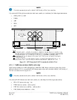
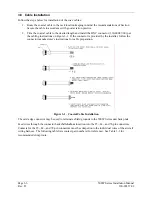
Use the dimensions shown in Figure F-1 to prepare the mounting holes for the 500W Series unit. You
may also use the 500W Series unit mounting rack itself as a template for drilling the mounting holes.
1. The back plate of the rack may optionally be removed for ease of mounting in the aircraft panel.
To do so, remove the two #4-40 screws, tilt the back plate away from the tray, and then slide the
back plate to the side.
2. Figure F-1 shows outline dimensions for the aviation rack for the various 500W Series units.
Install the rack in a rectangular 6.320 inches x 4.600 inches hole (or gap between units) in the
instrument panel (see Figure F-4). The lower-front lip of the rack should be flush with, or extend
slightly beyond, the finished aircraft panel.
NOTE
If the front lip of the mounting rack is behind the surface of the aircraft panel,
the 500W Series unit connectors may not fully engage.
Make sure that no screw heads or other obstructions prevent the unit from fully
engaging in the rack (see the “Connector Engagement Test,” Section 5.2).
Exercise caution when installing the rack into the instrument panel. The rack is
designed to facilitate removal of the 500W Series unit for use in Demo Mode
outside the aircraft. Deformation of the rack may make it difficult to install and
remove the 500W Series unit.
3. Install the rack in the aircraft panel using six #6-32 flat head screws and six self-locking nuts.
The screws are inserted from the inside through the holes in the sides of the rack.
4. If the back plate was previously removed (see Step 1), replace the back plate by positioning the
tabs on the back plate in the slots of the left side of the rack (viewing it from the cockpit) and
attaching it by replacing the two #4-40 screws.
3.9.2
500W Series Unit Insertion and Removal
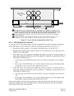
It may be necessary to insert the hex drive tool into the access hole and rotate the mechanism 90°
counterclockwise to insure correct position prior to placing the unit in the rack. The 500W Series unit is
installed in the rack by sliding it straight in until it stops, about 1 inch short of the final position. A 3/32-
inch hex drive tool is then inserted into the access hole at the bottom of the unit face. Rotate the hex tool
clockwise while pressing on the left side of the bezel until the unit is firmly seated in the rack.
To remove the unit from the rack, insert the hex drive tool into the access hole on the unit face and rotate
counterclockwise until the unit is forced out about 3/8 inches and can be freely pulled from the rack.
Be sure not to over tighten the unit into the rack. The application of hex drive tool torque exceeding
15 in-lbs can damage the locking mechanism.
3.9.3 Unit
Replacement
Whenever the 500W Series unit is removed or reinstalled, verify that the unit power-up self-test sequence
is successfully completed and no failure messages are annunciated. Section 5.5.1 outlines the power-up
self-test sequence.
Summary of Contents for GNS 530W
Page 2: ...500W Series Installation Manual 190 00357 02 Rev D...
Page 130: ...Page 7 4 500W Series Installation Manual Rev D 190 00357 02 This Page Intentionally Left Blank...
Page 132: ...Page 8 2 500W Series Installation Manual Rev D 190 00357 02 This Page Intentionally Left Blank...
Page 134: ...Page A 2 500W Series Installation Manual Rev D 190 00357 02 This Page Intentionally Left Blank...
Page 136: ...Page B 2 500W Series Installation Manual Rev D 190 00357 02 This Page Intentionally Left Blank...
Page 137: ...500W Series Installation Manual Page C 1 190 00357 02 Rev D Appendix C RESERVED...
Page 138: ...Page C 2 500W Series Installation Manual Rev D 190 00357 02 This Page Intentionally Left Blank...
Page 148: ...Page E 6 500W Series Installation Manual Rev D 190 00357 02 This Page Intentionally Left Blank...
Page 150: ...Page F 2 500W Series Installation Manual Rev D 190 00357 02 This Page Intentionally Left Blank...
Page 160: ...Page G 6 500W Series Installation Manual Rev D 190 00357 02 This Page Intentionally Left Blank...
Page 162: ...Page H 2 500W Series Installation Manual Rev D 190 00357 02 This Page Intentionally Left Blank...
Page 188: ...Page H 28 500W Series Installation Manual Rev D 190 00357 02 Figure H 16 GTX 330 Interconnect...
Page 194: ...Page H 34 500W Series Installation Manual Rev D 190 00357 02 Figure H 20 RMI OBI Interconnect...
Page 198: ...Page H 38 500W Series Installation Manual Rev D 190 00357 02 Figure H 24 TAWS Interconnect...
Page 211: ...500W Series Installation Manual Page H 51 190 00357 02 Rev D Figure H 33 Switches Interconnect...
Page 215: ......
Page 216: ......


