


Page iv
500W Series Installation Manual
Rev. D
190-00357-02
E.3
Icarus Altitude Sentence .............................................................................................................. E-1
E.4
Shadin Fuel Flow Sentence.......................................................................................................... E-2
E.5
ARNAV / EI Fuel Flow Sentence ................................................................................................ E-2
E.6
Shadin Fuel/Airdata Computer Sentence ..................................................................................... E-3
A
PPENDIX
F
MECHANICAL
DRAWINGS ........................................................................................ F-1
F.1
Drawing List................................................................................................................................. F-1
A
PPENDIX
G
APPROVED
EQUIPMENT ............................................................................................G-1
G.1
Audio Panels ................................................................................................................................G-1
G.2
Air Data Computer .......................................................................................................................G-1
G.3
Altitude Serializer or Fuel/Air Data.............................................................................................G-2
G.4
Autopilots.....................................................................................................................................G-2
G.5
Encoding Altimeter or Blind Encoder (Gray Code) ....................................................................G-2
G.6
EFIS Displays...............................................................................................................................G-3
G.7
EHSI .............................................................................................................................................G-3
G.8
IRU/AHRS ...................................................................................................................................G-3
G.9
NAV Indicator..............................................................................................................................G-4
G.10
Weather, Traffic and Terrain ...................................................................................................G-4
G.11
DME.........................................................................................................................................G-4
G.12
CDI/HSI Source Selection Annunciators.................................................................................G-5
G.13
Multifunction Displays ............................................................................................................G-5
A
PPENDIX
H
STC
APPROVED
INTERCONNECT
DIAGRAMS ......................................................H-1
H.1.
Introduction..............................................................................................................................H-1
H.2.
Drawing List ............................................................................................................................H-1
LIST OF FIGURES
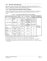
Figure 2-1. GPS Antenna Installation Considerations ............................................................................. 2-5
Figure 2-2. Source Selection Annunciation Field of View ...................................................................... 2-9
Figure 2-3. GPS Navigation/TAWS Annunciation Field of View......................................................... 2-10
Figure 3-1. Coaxial Cable Installation ..................................................................................................... 3-6
Figure 5-1. MAIN ARINC 429 CONFIG Page........................................................................................ 5-2
Figure 5-2. MAIN RS-232 CONFIG Page ............................................................................................... 5-5
Figure 5-3. MAIN SYSTEM CONFIG Page ........................................................................................... 5-6
Figure 5-4. MAIN SYSTEM CONFIG Page ........................................................................................... 5-7
Figure 5-5
.
MAIN SYSTEM CONFIG Page ........................................................................................... 5-7
Figure 5-6. MAIN INPUTS Page ............................................................................................................. 5-8
Figure 5-7. INSTRUMENT PANEL SELF-TEST Page.......................................................................... 5-8
Figure 5-8. MAIN LIGHTING Page ........................................................................................................ 5-9
Figure 5-9. Main Lighting Page with Alternate Source ......................................................................... 5-10
Figure 5-10. GPS DATE/TIME Page..................................................................................................... 5-10
Figure 5-11. MAIN DISCRETE I/O Page.............................................................................................. 5-11
Figure 5-12. MAIN CDI/OBS CONFIG Page ....................................................................................... 5-12
Figure 5-13. COM SETUP Page ............................................................................................................ 5-14
Figure 5-14. VOR DISCRETE INPUTS Page ....................................................................................... 5-15
Figure 5-15. VOR/LOC/GS CDI Page ................................................................................................... 5-16
Figure 5-16. VOR/LOC/GS ARINC 429 CONFIG Page....................................................................... 5-17
Figure 5-17. Measurement of GPS Vertical Offset................................................................................ 5-18
Figure 5-18. GPS Vertical Offset Page .................................................................................................. 5-18
Figure 5-19. STORMSCOPE CONFIG Page......................................................................................... 5-19
Summary of Contents for GNS 530W
Page 2: ...500W Series Installation Manual 190 00357 02 Rev D...
Page 130: ...Page 7 4 500W Series Installation Manual Rev D 190 00357 02 This Page Intentionally Left Blank...
Page 132: ...Page 8 2 500W Series Installation Manual Rev D 190 00357 02 This Page Intentionally Left Blank...
Page 134: ...Page A 2 500W Series Installation Manual Rev D 190 00357 02 This Page Intentionally Left Blank...
Page 136: ...Page B 2 500W Series Installation Manual Rev D 190 00357 02 This Page Intentionally Left Blank...
Page 137: ...500W Series Installation Manual Page C 1 190 00357 02 Rev D Appendix C RESERVED...
Page 138: ...Page C 2 500W Series Installation Manual Rev D 190 00357 02 This Page Intentionally Left Blank...
Page 148: ...Page E 6 500W Series Installation Manual Rev D 190 00357 02 This Page Intentionally Left Blank...
Page 150: ...Page F 2 500W Series Installation Manual Rev D 190 00357 02 This Page Intentionally Left Blank...
Page 160: ...Page G 6 500W Series Installation Manual Rev D 190 00357 02 This Page Intentionally Left Blank...
Page 162: ...Page H 2 500W Series Installation Manual Rev D 190 00357 02 This Page Intentionally Left Blank...
Page 188: ...Page H 28 500W Series Installation Manual Rev D 190 00357 02 Figure H 16 GTX 330 Interconnect...
Page 194: ...Page H 34 500W Series Installation Manual Rev D 190 00357 02 Figure H 20 RMI OBI Interconnect...
Page 198: ...Page H 38 500W Series Installation Manual Rev D 190 00357 02 Figure H 24 TAWS Interconnect...
Page 211: ...500W Series Installation Manual Page H 51 190 00357 02 Rev D Figure H 33 Switches Interconnect...
Page 215: ......
Page 216: ......


