


Page 5-18
500W Series Installation Manual
Rev. D
190-00357-02
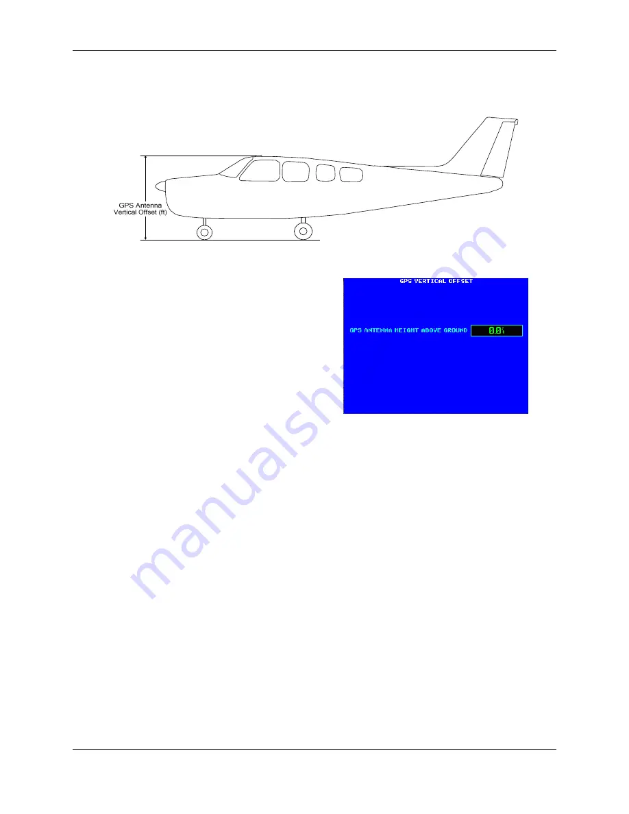
5.3.14 GPS Vertical Offset
The GPS Vertical Offset setup function is used to enter the height above ground of the GPS antenna.
Prior to proceeding, measure the GPS antenna vertical offset (to the nearest foot) as shown in Figure
5-17.
Figure 5-17. Measurement of GPS Vertical Offset
Use the large and small knobs to enter the offset value
and press ENT to save.
Figure 5-18. GPS Vertical Offset Page
Summary of Contents for GNS 530W
Page 2: ...500W Series Installation Manual 190 00357 02 Rev D...
Page 130: ...Page 7 4 500W Series Installation Manual Rev D 190 00357 02 This Page Intentionally Left Blank...
Page 132: ...Page 8 2 500W Series Installation Manual Rev D 190 00357 02 This Page Intentionally Left Blank...
Page 134: ...Page A 2 500W Series Installation Manual Rev D 190 00357 02 This Page Intentionally Left Blank...
Page 136: ...Page B 2 500W Series Installation Manual Rev D 190 00357 02 This Page Intentionally Left Blank...
Page 137: ...500W Series Installation Manual Page C 1 190 00357 02 Rev D Appendix C RESERVED...
Page 138: ...Page C 2 500W Series Installation Manual Rev D 190 00357 02 This Page Intentionally Left Blank...
Page 148: ...Page E 6 500W Series Installation Manual Rev D 190 00357 02 This Page Intentionally Left Blank...
Page 150: ...Page F 2 500W Series Installation Manual Rev D 190 00357 02 This Page Intentionally Left Blank...
Page 160: ...Page G 6 500W Series Installation Manual Rev D 190 00357 02 This Page Intentionally Left Blank...
Page 162: ...Page H 2 500W Series Installation Manual Rev D 190 00357 02 This Page Intentionally Left Blank...
Page 188: ...Page H 28 500W Series Installation Manual Rev D 190 00357 02 Figure H 16 GTX 330 Interconnect...
Page 194: ...Page H 34 500W Series Installation Manual Rev D 190 00357 02 Figure H 20 RMI OBI Interconnect...
Page 198: ...Page H 38 500W Series Installation Manual Rev D 190 00357 02 Figure H 24 TAWS Interconnect...
Page 211: ...500W Series Installation Manual Page H 51 190 00357 02 Rev D Figure H 33 Switches Interconnect...
Page 215: ......
Page 216: ......


