background image

Av. Kit Install. Manual
190-00026-00 Rev. Q
Page 15

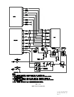
FIGURE 1-2 INTERCONNECT SCHEMATIC

Summary of Contents for GPS 150

Page 1: ...Av Kit Install Manual 190 00026 00 Rev Q Page 1 GPS 150 INSTALLATION MANUAL GARMIN INTERNATIONAL INC PART NUMBER 190 00026 00 1200 E 151st STREET REVISION Q 3 APRIL 1998 OLATHE KANSAS 66062 3426 ...

Page 2: ...3 1 6 Rev F 23 July 1993 Reverse Pin locations on Fig 1 1 2 3 5 1 Rev G 18 Aug 1993 Add Altitude Serializer interface details 2 4 7 0 Rev H 15 Oct 1993 Remove Warning Low from Pin out improve Super Flag description add rack dimension 3 4 0 4 Rev J 12 Sept 1994 Chg designation to pin 12 on arrival alarm annunciator 3 7 7 7 Rev K 30 Dec 1994 Add additional fuel flow options remove old antenna option...

Page 3: ...LECTRICAL BONDING 2 1 4 ANTENNA LIMITATIONS 2 1 5 VHF COMM INTERFERENCE 2 2 RACK CONSIDERATIONS 2 2 1 ACCESSIBILITY 2 3 CABLING AND WIRING 2 4 COOLING AIR 2 5 ANNUNCIATORS 2 6 EXTERNAL ALTITUDE INPUT SECTION 3 INSTALLATION PROCEDURE 3 1 INSTALLATION ACCESSORIES 3 2 ANTENNA INSTALLATION 3 3 CABLE INSTALLATION 3 4 RACK INSTALLATION 3 5 GPS 150 INSTALLATION AND REMOVAL 3 6 PLACARD SECTION 4 CHECKOUT ...

Page 4: ...ATION CONSIDERATIONS 2 2 GPS INSTALLATION CONSIDERATIONS 3 1 STUD MOUNT GA 56 INSTALLATION 3 2 FLANGE MOUNT GA 56 INSTALLATION 3 3 COAX CABLE INSTALLATION 3 4 AVIATION RACK DIMENSIONS 3 5 AVIATION RACK INSTALLATION A 1 FUNCTIONAL BLOCK DIAGRAM A 2 FUSELAGE STATIONS AND WEIGHT BALANCE DATA A 3 PANEL LAYOUT AND BREAKER LOCATION A 4 WIRING DIAGRAM ...

Page 5: ...Rack Weight 14 oz Max Air Speed Subsonic Structural rating for antenna 1 2 2 OPERATIONAL CHARACTERISTICS Operating Temperature Range 20 o C to 55 o C Humidity 95 non condensing Altitude Range 1 500 to 50 000 ft Power Input 10 to 33 VDC 5 watts Max 1 2 3 INTERFACES The GPS 150 provides interfaces to various general aviation instruments Figure 1 1 defines the function of each pin on the 37 pin DSUB ...

Page 6: ...ng interface Pin 19 on GARMIN PC software or NMEA 0183 version 2 0 compatible mapping device Conforms to the EIA specification RS 232C RS232 chan 1 input data Input capable of receiving serial altitude data from Pin 17 either an ICARUS Instruments 3000 Shadin Company formerly Rosetta MicroAvionics 8800T 9000T or 9200T series altitude serializer encoder Shadin 91204XT 91053XT Series Fuel management...

Page 7: ...distortion caused by the blades 2 1 2 NOISE SOURCES The antenna should be located at least 3 ft from transmitting antennas such as VHF Comm HF transmitter DME Transponder and Radar Cabling for the GPS 150 should not be routed near components or cabling which are sources of electrical noise 2 1 3 ELECTRICAL BONDING No special precautions need to be taken to provide a bonding path between the antenn...

Page 8: ...d 10dB at 1 5 GHz for the specific installation Check that there is ample space for the cabling and mating connectors Avoid sharp bends in cabling and routing near aircraft control cables 2 4 COOLING AIR Cooling air is not required for the GPS 150 however as with any electronic equipment reduced operating temperature can contribute to increased reliability Additionally location of the GPS 150 in a...

Page 9: ... make the antenna cable or it can be fabricated by the installer from materials meeting the requirements of paragraph 2 3 DATA BASE OPTIONS 010 10038 00 MEMORY CARD AMERICAS DATABASE 010 10038 01 MEMORY CARD INTERNATIONAL DATABASE 010 10038 02 MEMORY CARD WORLDWIDE DATABASE 010 10032 03 MEMORY CARD USER MISCELLANEOUS OPTIONS 190 00048 00 GPS 150 PILOT S GUIDE 190 00048 01 GPS 150 QUICK REFERENCE G...

Page 10: ...mmendations of Section 2 Secure the cable in accordance with good aviation practice B Trim the coaxial cable to the desired length and install the BNC connector 330 00087 00 per the cabling instructions on Figure 3 3 If the connector is provided by the installer follow the connector manufacturer s instructions for cable preparation C Contacts for the 37 pin connector must be crimped into the indiv...

Page 11: ... To remove the unit from the rack insert the hex drive tool into the access hole on the unit face and rotate counter clockwise until the unit is forced out about 3 4 inch and can be freely pulled from the rack Be sure not to over tighten the unit into the rack The application of hex drive tool torque exceeding 15 in lbs can damage the locking mechanism 3 6 PLACARD After completing the installation...

Page 12: ... IN VIEW Ensure CDI flag is in view OUT OF VIEW Ensure CDI flag is out of view SUPERFLAG IN VIEW Ensure superflag is in view OUT OF VIEW Ensure superflag is out of view Select the OBI Test Page by removing the cursor from the CDI Test Page and turning the outer knob one detent to the right Using the controls on the GPS 150 front panel make the selections indicated below and verify the interfaces a...

Page 13: ...the hangar facility and well away from buildings or other obstructions that might interfere with satellite signal reception With power applied to the aviation rack turn the GPS 150 on The Self Test Page will be displayed followed by the Data Base Page Upon approval of the Data Base Page the Satellite Status Page will be displayed If unable to acquire satellites relocate the aircraft away from obst...

Page 14: ...Av Kit Install Manual 190 00026 00 Rev Q Page 14 FIGURE 1 1 PINOUT DEFINITION ...

Page 15: ...Av Kit Install Manual 190 00026 00 Rev Q Page 15 FIGURE 1 2 INTERCONNECT SCHEMATIC ...

Page 16: ...6 00 Rev Q Page 16 Maintain 6 16 cm compass safe distance FIG 2 2 GPS INSTALLATION CONSIDERATIONS FIG 2 1 ANTENNA INSTALLATION CONSIDERATIONS Antenna masked by vertical fin T tail or dorsal fin Antenna must be on top of aircraft OK ...

Page 17: ...Av Kit Install Manual 190 00026 00 Rev Q Page 17 FIG 3 1 STUD MOUNT GA 56 ANTENNA INSTALLATION ...

Page 18: ...Av Kit Install Manual 190 00026 00 Rev Q Page 18 FIGURE 3 2 FLANGE MOUNT GA 56 ANTENNA INSTALLATION ...

Page 19: ...Av Kit Install Manual 190 00026 00 Rev Q Page 19 FIGURE 3 3 COAX CABLE INSTALLATION ...

Page 20: ...Av Kit Install Manual 190 00026 00 Rev Q Page 20 FIGURE 3 4 AVIATION RACK DIMENSIONS ...

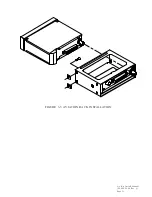
Page 21: ...Av Kit Install Manual 190 00026 00 Rev Q Page 21 FIGURE 3 5 AVIATION RACK INSTALLATION ...

Page 22: ...TION The GPS 150 aviation rack is to be installed in the instrument panel radio rack as shown in figure A 3 The controls and display of the GPS 150 must be readily visible to the pilot when seated at the controls To install the aviation rack position it in the instrument panel in the desired position assuring that the front is not twisted out of square Match drill the flanges on the radio rack to ...

Page 23: ...UT When the installation is complete conduct a post installation checkout as specified in section 4 of the Installation Manual being sure to check the proper operation of all connected instruments 4 0 RETURN TO SERVICE After installation a new weight and balance must be computed to show the GPS 150 components The aircraft should then be returned to service by completion of FAA form 337 by an appro...

Page 24: ...Av Kit Install Manual 190 00026 00 Rev Q Page 24 FIG A 1 FUNCTIONAL BLOCK DIAGRAM ...

Page 25: ...Av Kit Install Manual 190 00026 00 Rev Q Page 25 FIG A 2 FUSELAGE STATIONS AND WEIGHT AND BALANCE DATA ...

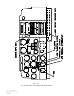
Page 26: ...Av Kit Install Manual 190 00026 00 Rev Q Page 26 FIG A 3 PANEL LAYOUT AND BREAKER LOCATION ...

Page 27: ...Av Kit Install Manual 190 00026 00 Rev Q Page 27 FIG A 4 WIRING DIAGRAM ...

Page 28: ...contacts with color coded barrels The following figures can be used to identify which type contact you have When working with the stamped crimp type contacts the following tools should be used Tools 37 position connectors Supplier Crimp Tool Extraction Tool Amp 58448 2 91067 22 ITT Cannon 995 2000 000 980 0008 124 Cinch HTD 544 CIET 20 HDB Part numbers shown are not maintained by Garmin and conseq...

Page 29: ... Manual 190 00026 00 Rev Q Page 29 APPENDIX C STC PERMISSION Consistent with N8110 69 or Order 8110 4 Aviation Authority approved installers are hereby granted permission to use STC SA00066WI data to modify aircraft ...

Page 30: ...Av Kit Install Manual 190 00026 00 Rev Q Page 30 ...

Reviews: