background image

190-00228-08 

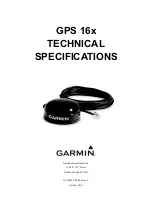
GPS 16x Technical Specifications  

Rev. C 

Page 4 

1.5  TECHNICAL SPECIFICATIONS 

Specifications are subject to change without notice. 

1.5.1  Physical Characteristics 

1.5.1.1  Size 

3.58” (91.0 mm) diameter, 1.65” (42 mm) high 

1.5.1.2  Weight 


GPS 16xLVS only: 


6.0 oz (169 g) 


GPS 16xHVS only: 


6.1 oz (174 g) 


GPS 16xLVS with 5-meter cable: 

11.3 oz (320 g) 


GPS 16xHVS with 5-meter cable:  

11.5 oz (325 g) 


GPS 16xLVS & 16xHVS cable alone:  

5.3 oz (151 g) 

1.5.1.3  Cable 

GPS 16xLVS & 16xHVS: Black PVC-jacketed, 5-meter, foil-shielded, 8-conductor 28 AWG with RJ-45 

termination 

1.5.1.4  Color 

GPS 16xLVS & 16xHVS: Black with white logos 

1.5.1.5  Case Material 

Polycarbonate thermoplastic that is waterproof to IEC 60529 IPX7 level (immersion in 1 meter of water for 30 

minutes). 

1.5.2  Electrical Characteristics 

1.5.2.1  Input Voltage 


GPS 16xLVS: 3.3 Vdc to 6.0 Vdc regulated, <100 mV ripple 


GPS 16xHVS & 17HVS: 8.0 Vdc to 40 Vdc unregulated 

1.5.2.2  Input Current  


GPS 16xHVS:  100 mA @ 8 Vdc 


65 mA @ 12 Vdc 


28 mA @ 40 Vdc 


GPS 16xLVS:  90 mA typical 

1.5.2.3  Standby Current 

<10 µA for all GPS 16x models 

1.5.2.4  GPS Receiver Sensitivity 

-185 dBW minimum 

1.5.3  Environmental Characteristics 


Operating Temperature:  -30°C to +80°C (-22°F to +176°F) 


Storage Temperature: 

-40°C to +80°C (-40°F to +176°F) 

Summary of Contents for GPS 16x

Page 1: ...GPS 16x TECHNICAL SPECIFICATIONS Garmin International Inc 1200 E 151st Street Olathe KS 66062 USA 190 00228 08 Revision C October 2011...

Page 2: ...c storage medium to be viewed and to print one copy of this manual or of any revision hereto provided that such electronic or printed copy of this manual must contain the complete text of this copyrig...

Page 3: ...2 GPS 16x Wiring and Pinouts 7 2 1 GPS 16x Pinout 7 2 2 GPS 16x Wiring Diagrams 8 3 Mechanical Characteristics Mounting 9 3 1 GPS 16x Flush Mount 9 3 2 GPS 16x Optional Magnetic Mount 10 4 Software In...

Page 4: ...eview 26 Ephemeris Download Procedure 27 TX Packet Ephemeris Data Request 27 RX Packet Acknowledgement 27 RX Packet Number of Data Packets to Expect 27 TX Packet Acknowledgement 27 RX Packet Ephemeris...

Page 5: ...to comply with the limits for a Class B digital device pursuant to part 15 of the FCC rules These limits are designed to provide reasonable protection against harmful interference in a residential ins...

Page 6: ...TING FROM THE USE MISUSE OR INABILITY TO USE THE PRODUCT OR FROM DEFECTS IN THE PRODUCT SOME STATES DO NOT ALLOW THE EXCLUSION OF INCIDENTAL OR CONSEQUENTIAL DAMAGES SO THE ABOVE LIMITATIONS MAY NOT A...

Page 7: ...clear view of the GPS satellites The system may communicate with the GPS via an asynchronous serial communications port Internal FLASH memory allows the GPS to retain critical data such as satellite o...

Page 8: ...28 AWG with RJ 45 termination 1 5 1 4 Color GPS 16xLVS 16xHVS Black with white logos 1 5 1 5 Case Material Polycarbonate thermoplastic that is waterproof to IEC 60529 IPX7 level immersion in 1 meter...

Page 9: ...lity Dynamics 999 knots velocity only limited at altitude greater than 60 000 feet 3g dynamics 1 5 5 Interfaces True RS 232 output asynchronous serial input compatible with RS 232 or TTL voltage level...

Page 10: ...190 00228 08 GPS 16x Technical Specifications Rev C Page 6 1 5 5 3 PPS 1 Hz pulse programmable width 1 s accuracy 1 5 5 4 Power Control Off Open circuit On Ground or pull to low logic level 0 3 volts...

Page 11: ...range 25 Vdc 25 This input may also be directly connected to standard 3 to 5 Vdc CMOS logic The low signal voltage requirement is 0 6 V and the high signal voltage requirement is 2 4 Vdc Input impedan...

Page 12: ...8 08 GPS 16x Technical Specifications Rev C Page 8 2 2 GPS 16x WIRING DIAGRAMS Figure 1 Computer Serial Port Interconnection Figure 2 PDA Serial Port Interconnection Figure 3 Basic NMEA Device Interco...

Page 13: ...6x Technical Specifications Rev C Page 9 3 3 1 GPS 16x FLUSH MOUNT MECHANICAL CHARACTERISTICS MOUNTING Figure 4 GPS 16x Flush Mount Dimensions 1 65 inches 42 mm 3 58 inches 91 mm 2 44 inches 62 mm 120...

Page 14: ...190 00228 08 GPS 16x Technical Specifications Rev C Page 10 3 2 GPS 16x OPTIONAL MAGNETIC MOUNT Figure 5 Optional GPS 16x Magnetic Mount Magnetic Mount M4 Flat Head Screws 3 each...

Page 15: ...onfiguration parameter All sentences received by the GPS sensor must be terminated with CR LF the ASCII characters for carriage return 0D hexadecimal and line feed 0A hexadecimal The checksum hh is us...

Page 16: ...lues Current default values can also be obtained by sending PGRMCE to the GPS sensor PGRMC 1 2 3 4 5 6 7 8 9 10 11 12 13 14 hh CR LF 1 Fix mode A Automatic 3 3D exclusively 2 Altitude above below mean...

Page 17: ...itialization Information PGRMI If the GPS sensor is in the Binary data mode it is necessary to send the following eight byte data stream to temporarily change the data format to NMEA 0183 Then follow...

Page 18: ...nical Specifications Rev C Page 14 PGRMO G will cause the COM port to change to Garmin Data Transfer format for the duration of the power cycle You must enable Garmin Data Transfer format to update th...

Page 19: ...itted per second Sentence Output by Default Maximum Characters GPRMC 74 GPGGA 82 GPGSA 66 GPGSV 70 PGRME 35 GPGLL 44 GPVTG 42 PGRMV 32 PGRMF 82 PGRMB 40 PGRMID 82 PGRMM 32 PGRMT 50 Baud Table 2 NMEA 0...

Page 20: ...d will be only 59 seconds long In this case the GPS sensor will not transmit the time of day 0h 0m 0s the zero second for the day from which the leap second is removed GPRMC 235959 A 3851 3650 N 09447...

Page 21: ...ll be null if unused 4 2 7 Recommended Minimum Specific GPS TRANSIT Data RMC GPRMC 1 2 3 4 5 6 7 8 9 10 11 12 hh CR LF 1 UTC time of position fix hhmmss format 2 Status A Valid position V NAV receiver...

Page 22: ...gitude dddmm mmmm format leading zeros will be transmitted 9 Longitude hemisphere E or W 10 Mode M Manual A Automatic 11 Fix type 0 no fix 1 2D fix 2 3D fix 12 Speed over ground 0 to 1851 kilometers h...

Page 23: ...this model and is included only for backwards compatibility 7 DGPS fix source R RTCM W WAAS N Non DGPS Fix 8 DGPS mode A Automatic W WAAS Only R RTCM Only N None DGPS disabled 4 3 BAUD RATE SELECTION...

Page 24: ...te and Erromango Islands 14 BERMUDA 1957 Bermuda Islands 15 BOGOTA OBSERVATORY Colombia 16 CAMPO INCHAUSPE Argentina 17 CANTON ASTRO 1966 Phoenix Islands 18 CAPE CANAVERAL Florida Bahama Islands 19 CA...

Page 25: ...H AMERICAN 1927 Bahamas excluding San Salvador Island 57 NORTH AMERICAN 1927 Central America Belize Costa Rica El Salvador Guatemala Honduras Nicaragua 58 NORTH AMERICAN 1927 Canal Zone 59 NORTH AMERI...

Page 26: ...outh Chile 87 SANTO DOS Espirito Santo Island 88 SAO BRAZ Sao Miguel Santa Maria Islands Azores 89 SAPPER HILL 1943 East Falkland Island 90 SCHWARZECK Namibia 91 SOUTHEAST BASE Porto Santo and Madeira...

Page 27: ...yte 10 hex and an end of transmission character 03 hex Note If RTCM 104 differential data is sent to the GPS sensor the board will reset the Garmin Binary Output Data baud rate to the same baud rate u...

Page 28: ...ce vehicle identification 1 32 and 33 64 for WAAS uint16 snr signal to noise ratio uint8 elev satellite elevation in degrees uint16 azmth satellite azimuth in degrees uint8 status status bit field cpo...

Page 29: ...and initialize static variables static char in_que 256 static int in_que_ptr 0 static rx_state_type rx_state DAT void add_to_que char data define DLE_BYTE 0x10 define ETX_BYTE 0x03 if rx_state DAT if...

Page 30: ...nit is in Garmin binary format transmitted and received packets are structured as follows Byte Description Name Notes Packet Delimiter DLE 0x10 Packet ID type ID Packet type Data Size SIZE Number of b...

Page 31: ...ID IOP_ACK_BYTE 0x06 Number of bytes in data SIZE 0x02 Request to D L ephemeris IOP_CMND_DATA 0x0A Pad DATA 0x00 Checksum calculation CHKSUM Delimiter DLE 0x10 End of packet ETX 0x03 Then the unit wil...

Page 32: ...eris data record for SPC sint16 wn week number weeks float toc reference time of clock parameters s float toe reference time of ephemeris parameters s float af0 clock correction coefficient group dela...

Page 33: ...emp EphStruct af2 float m_TempArray IDX_EPH_AF2 pTemp EphStruct ura float m_TempArray IDX_EPH_URA cnvt_ieee_double long m_TempArray IDX_EPH_E pTemp EphStruct e double m_TempArray IDX_EPH_E cnvt_ieee_d...

Page 34: ..._M0 52 define IDX_EPH_W 60 define IDX_EPH_OMG0 68 define IDX_EPH_I0 76 define IDX_EPH_ODOT 84 define IDX_EPH_IDOT 88 define IDX_EPH_CUS 92 define IDX_EPH_CUC 96 define IDX_EPH_CIS 100 define IDX_EPH_C...

Page 35: ...ds SNSRCFG exe is included in the software update download Selecting a Model Double click SNSRCFG exe The Set Base Model to window appears Select the radio button next to the type of Garmin sensor you...

Page 36: ...disconnect from the sensor Config Menu The Config Configuration Menu allows you to configure the sensor as it is connected Sensor Configuration F6 Opens the Sensor Configuration window shown to the ri...

Page 37: ...g box You must locate both the rgn file and the updater exe file View Menu The View Menu allows you to view the NMEA sentences transmitted by the sensor You can also customize how the program looks by...

Reviews: