190-02207-A2
GPS 175/GNX 375/GNC 355 Part 23 AML STC Maintenance Manual
Rev. 3
Page 5-17
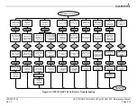
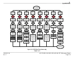
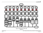
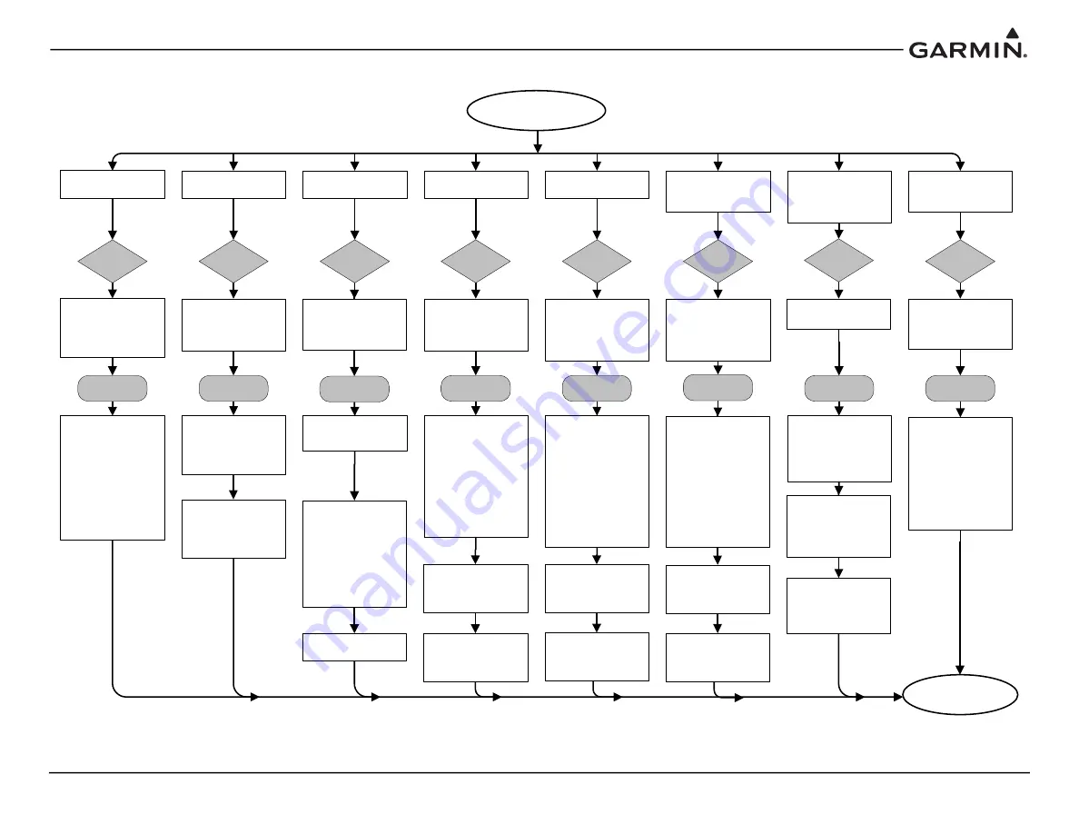
Figure 5-7 GNC 355 COM Alert Troubleshooting
Radio needs service.
Radio may be
inoperative.
Push-to-talk key is
stuck.
Remote transfer key is
stuck.
Remote frequency
increment key is stuck.
Remote frequency
decrement key is
stuck.
GNC 355 COM Alerts
Cause
Overtemp or
undervoltage.
Reducing transmitter
power.
Locked to 121.5 MHz.
Hold remote COM
transfer key to exit
Corrective
Action
Cause
Cause
Cause
Cause
Cause
A failure has been
detected in the COM
transceiver. The
transceiver may still
be usable.
The GNC 355 is not
able to communicate
with its COM
transceiver.
Press the
PTT
switch
to cycle its operation.
The
COM remote
transfer key
is stuck
in the enabled or
pressed state.
The
COM remote
frequency increment
key is stuck in the
enabled or pressed
state.
The
COM remote
frequency decrement
key is stuck in the
enabled or pressed
state.
Ensure the fan is
functioning properly
and check for
adequate airflow
around the unit.
Corrective
Action
Corrective
Action
This message may
appear after
operations in
Configuration mode.
Cycle power to the
entire GNC 355 (both
GPS/NAV and COM
circuit breakers) and
see if the message
has cleared.
Verify that COM
connector pins P3552-
43 and P3552-44 are
receiving aircraft
power.
Corrective
Action
Go to the
GNC
DIAGNOSTICS –
DISCRETE INPUTS
page in Configuration
mode and check that
the state of the input
changes when the
COM remote transfer
switch is pressed and
released.
If faults still exist,
contact Garmin.
Corrective
Action
Corrective
Action
The
COM remote
transfer
switch has
been pressed for at
least 2 seconds.
Corrective
Action
In Lockout mode, the
COM will tune the
active frequency to be
changed. COM
Lockout mode can be
exited by pressing the
COM remote transfer
switch for at least 2
seconds.
Cause
The
COM push-to-
talk
switch is stuck in
the enabled or
pressed state.
Corrective
Action
The COM is reporting
a high temperature.
Verify that COM
connector pins P3552-
37 and P3552-38 are
connected to aircraft
ground.
Go to the
GNC
DIAGNOSTICS –
DISCRETE INPUTS
page in Configuration
mode and check that
the state of the input
changes when the
PTT
switch is pressed
and released.
Verify the
PTT
switch
wiring is correct.
Verify the
COM
remote transfer
switch wiring is
correct.
Cause
Press the
COM
remote transfer
switch to cycle its
operation.
Go to the
GNC
DIAGNOSTICS –
DISCRETE INPUTS
page in Configuration
mode and check that
the state of the input
changes when the
COM remote
frequency increment
switch is pressed and
released.
Verify the
COM
remote frequency
increment
switch
wiring is correct.
Press the
COM
remote frequency
increment
switch to
cycle its operation.
Go to the
GNC
DIAGNOSTICS –
DISCRETE INPUTS
page in Configuration
mode and check that
the state of the input
changes when the
COM remote
frequency decrement
switch is pressed and
released.
Verify the
COM
remote frequency
decrement
switch
wiring is correct.
Press the
COM
remote frequency
decrement
switch to
cycle its operation.
Ensure the fan is
functioning properly
and check for
adequate airflow
around the unit.
Ensure that the COM
radio is receiving
adequate input voltage
(11-33 VDC).


