190-02207-A2
GPS 175/GNX 375/GNC 355 Part 23 AML STC Maintenance Manual
Rev. 3
Page 5-23
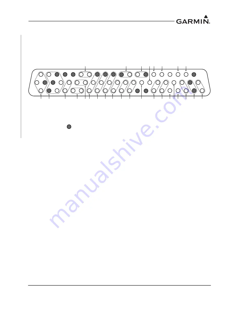
5.3 GPS 175 Connector Pinout Information
5.3.1 J1751 62-Pin HD-DSub
Figure 5-12 J1751 Connector (Looking at Unit)
T
+
P
P
F
B
A
O
U
O
+
H
L
N
N
R
R
B
D
O
+
L
21
42
D
is
cr
ete
Input (
2)
Li
ghti
ng B
us
APPR
(1
)
Pow
er
Input 1
Pow
er
G
round
A
T
A
R
S-
232 #3
CD
I
R
S-
232 #2
D
is
cr
ete
O
ut (
4)
I
O
I
I
62
+
I
B
A
C
onfi
g Modul
e
22
43
1
C
C
I
T
F
O
D
D
T
R
V
OB
S
R
S-
232 #1
B
D
emo Mode
(3)
TO
/F
R
O
M
Fl
ag
R
emote P
ow
er
O
n
LO
I (
2)
R
1P
PS
I/O
A
R
IN
C
42
9 T
X
A
R
INC
42
9
RX
2
AR
IN
C
429 R
X1
G
PS
Se
le
ct
(3
)
VD
I
HS
D
B
R
X
HS
D
B
TX
LO
C
Co
m
po
si
te
C
D
I V
alid
F
la
g
V
D
I V
al
id F
lag
D
is
cr
ete
Input (
1)
Ground
Numbers in ( ) for discrete I/O correspond to the I/O in the interconnect.


