GPS 500 Pilot’s Guide and Reference
SECTION 5
PROCEDURES
5-15
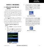
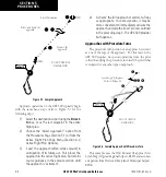
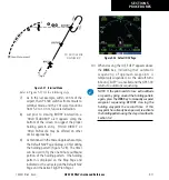
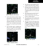
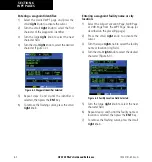
Refer to Figure 5-35 for the following steps.
3) Within 30 nm of KTOP, the GPS 500 switches
from enroute mode to terminal mode and the
CDI scale transitions from 5.0 to 1.0 nm, full
scale deflection.
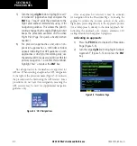
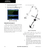
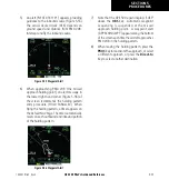
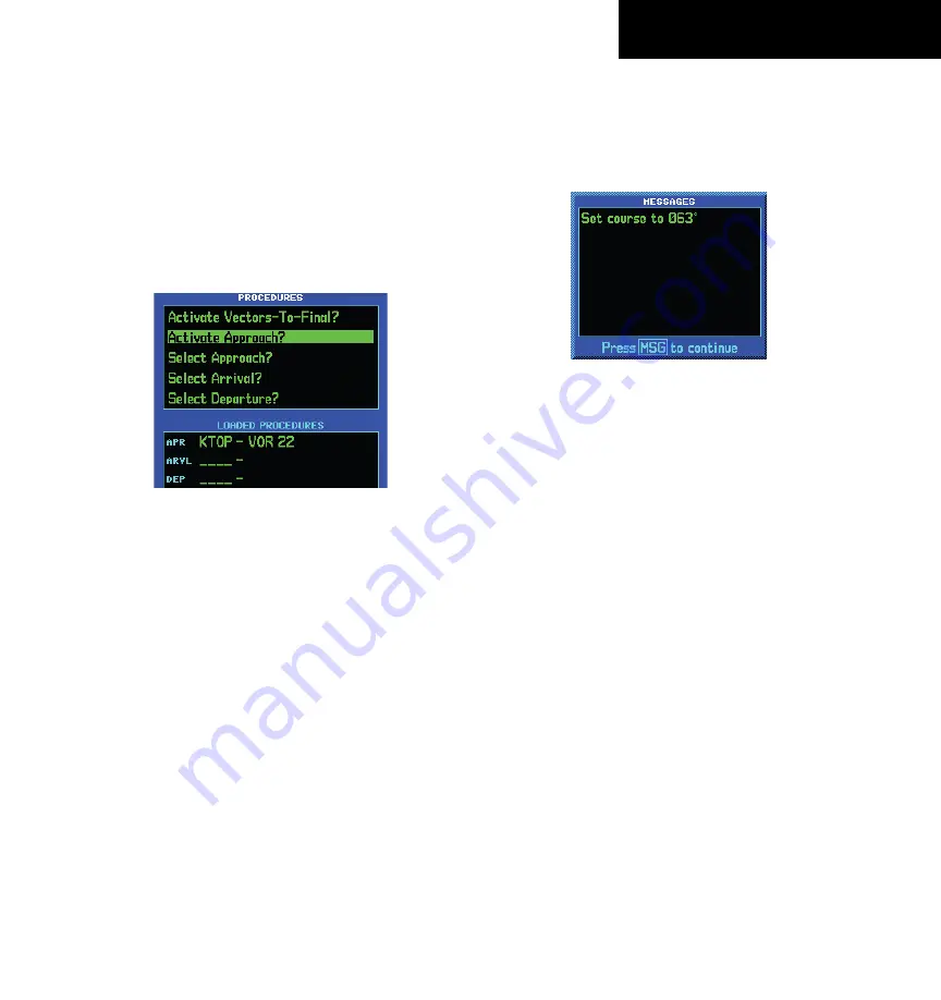
4) If the approach has not yet been activated
(in step 2 above), do so when cleared for the
approach (Figure 5-36).
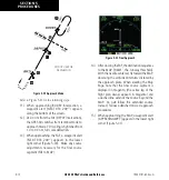
Figure 5-36 Procedures Page
5) When approaching the IAF (D258G), a waypoint
alert (‘NEXT DTK 353°’) appears along the
bottom of the screen. As the distance (DIS) to
the IAF approaches zero, the alert is replaced
by a turn advisory (‘TURN TO 353°’).
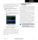
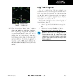
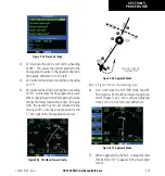
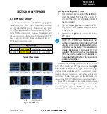
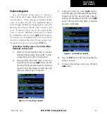
6) Follow the arc, when the course select setting
and desired track differ by more than 10°, a
‘Set course to ###°’ message appears on the
Message Page (Figure 5-37).
Figure 5-37 Message Window
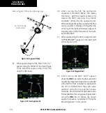
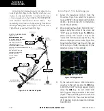
7) The next point in the approach is an intermediate
fix, labeled ‘D025G’. When approaching this
intermediate fix, a waypoint alert (‘NEXT DTK
205°’) appears along the bottom of the screen.
As the distance to this fix approaches zero, the
alert is replaced by a turn advisory (‘TURN TO
205°’). Dial this course into the CDI (or HSI)
using the OBS knob.
8) At 2.0 nm from the FAF (TOP VOR), the GPS
500 switches from terminal mode to approach
mode. CDI scaling is tightened from 1.0 to 0.3
nm, full scale deflection.
190-00181-60 Rev. G
Summary of Contents for GPS 500
Page 1: ...GPS 500 Pilot s Guide and Reference ...
Page 2: ......
Page 72: ...GPS 500 Pilot s Guide and Reference 4 16 SECTION 4 FLIGHT PLANS Blank Page 190 00181 60 Rev G ...
Page 98: ...GPS 500 Pilot s Guide and Reference SECTION 5 PROCEDURES 5 26 Blank Page 190 00181 60 Rev G ...
Page 134: ...GPS 500 Pilot s Guide and Reference 7 12 SECTION 7 NRST PAGES Blank Page 190 00181 60 Rev G ...
Page 255: ......

