background image

GPSMAP

®

 6000/7000 Series Owner’s Manual 

6

Device Configuration 

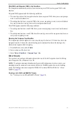
Wind VMG and Waypoint VMG in the Data Bars

The chartplotter automatically switches between showing wind VMG and waypoint VMG in the 

data bars.
Waypoint VMG appears under the following conditions:

The route leg section of the navigation data bar shows waypoint VMG when you are navigating a 

route or an Auto Guidance line.
The sailing data bar shows waypoint VMG when you are navigating a route or an Auto Guidance 

line, and you turn the route leg section of the navigation data bar off.

Wind VMG appears under the following conditions:

The sailing data bar shows wind VMG when you are not navigating a route or an Auto Guidance 

line.
The sailing data bar shows wind VMG when the route leg section of the navigation data bar is on 

and you are navigating a route.

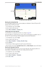
Showing the Compass Tape Data Bar

The compass tape data bar appears in a row across the top of a chart or a 3D chart view, above the 

navigation data bar. It shows the current heading, and an indicator that shows the bearing to the 

desired course appears while navigating.
1.  From the Home screen, select 

Charts

.

2.  Select a chart or a 3D chart view.
3.  Select 

Menu

 > 

Data Bars

 > 

Compass tape

 > 

on

.

Other Vessels

You can show and configure information about other vessels for the Navigation chart, the Fishing 

chart, Perspective 3D, or Mariner’s Eye 3D.

Note

: To configure Automatic Identification System (AIS) information for other vessels, your 

chartplotter must be connected to an external AIS device. MARPA requires the use of a heading 

sensor. The heading sensor must output the NMEA 0183 sentence HDM or HDG. See “About 

MARPA” (

page 77

).

Viewing a List of AIS and MARPA Threats

See “Viewing a List of AIS and MARPA Threats” (

page 18

).

Summary of Contents for GPSMAP 190-01120-00

Page 1: ...GPSMAP 6000 7000 series owner s manual...

Page 2: ...further that any unauthorized commercial distribution of this manual or any revision hereto is strictly prohibited Information in this document is subject to change without notice Garmin reserves the...

Page 3: ...ional settings Press and release the Power key to adjust the Backlight and Color Mode display settings Press and hold the Power key to turn on or off the chartplotter Manual Conventions In this manual...

Page 4: ...manac Data 46 Environmental Data 48 On boat Data 51 Device Configuration 57 Basic Device Configuration Questions 57 Simulator Mode 57 Turning the Chartplotter On Automatically 58 Display Configuration...

Page 5: ...l iii Introduction Screenshots 115 Viewing GPS Satellite Locations 115 System Information 115 NMEA 0183 and NMEA 2000 117 Product Registration 120 Contact Garmin 120 Declaration of Conformity 120 Soft...

Page 6: ......

Page 7: ...ted Getting Started Front and Back Panels GPSMAP 6012 and 6212 Front View GPSMAP 7015 and 7215 Front View Power key Automatic backlight sensor Range keys Rocker Soft keys MARK SELECT MENU and HOME but...

Page 8: ...wner s Manual Getting Started GPSMAP 6008 6208 6012 6212 7012 and 7212 Back View GPSMAP 7015 and 7215 Back View Network connectors NMEA 2000 connector NMEA 0183 connector Power connector Video Yellow...

Page 9: ...chartplotter the GPS receiver must collect satellite data and establish the current location When the chartplotter acquires satellite signals the signal strength bars at the top of the Home screen are...

Page 10: ...he SD card slot is located on the front of the chartplotter Open the access door insert the data card or the memory card into the slot and press the card until it clicks Press the data card or the mem...

Page 11: ...o in a two three or four field split screen page 28 Information shows information including tides currents celestial data user data information about other boats gauges and video page 46 Mark marks ed...

Page 12: ...ge 19 Mariner s Eye 3D shows a detailed three dimensional view from above and behind the boat for a visual navigation aid page 22 Fishing Chart removes navigational data from the chart and enhances bo...

Page 13: ...ter or other obstacles that may be in your path When using Go To a direct course and a corrected course may pass over land or shallow water Use visual sightings and steer to avoid land shallow water a...

Page 14: ...e screen so you can keep track of your present position The coordinate location of the cursor appears in the upper left corner of the map along with the distance and bearing of the cursor from your pr...

Page 15: ...object appears Select Navigate To to navigate to the selected location page 7 Select Create Waypoint to mark a waypoint at the cursor location Select Measure Distance to view the distance and bearing...

Page 16: ...n 4 Complete an action Select the button with the station name Select Review if more than one item is in the vicinity and select the button with the station name Detailed tide station information Tide...

Page 17: ...n is always up Changing the Map Zoom Detail You can adjust the amount of detail shown on the map at different zoom levels for the Navigation Chart or the Fishing Chart Note The Fishing chart is availa...

Page 18: ...ng line For the GPSMAP 6000 series use the Rocker or the Numeric Keypad to enter the distance For the GPSMAP 7000 series use the on screen keyboard Select Time to set the amount of time until you reac...

Page 19: ...nu Chart Setup Chart Appearance Symbols Select Fishing Chart Menu Chart Setup Chart Appearance 3 Complete an action Select Navaid Size to set the size of the navaid symbols shown on the map Select a s...

Page 20: ...on appears if the chartplotter is connected to a compatible marine wind sensor Note The Fishing chart is available with a preprogrammed BlueChart g2 Vision data card 1 From the Home screen select Char...

Page 21: ...SI speed and direction of the vessel appear beneath the target if the details setting has been set to Show page 17 If the AIS transmission from the vessel is lost a message banner appears Target has b...

Page 22: ...arget the projected course of the target is calculated based on the course over ground and the rate of turn information The direction in which the target is turning which is also based on the rate of...

Page 23: ...els Select Details Show to show details about AIS activated and MARPA tagged vessels Select Proj Heading to set the projected heading time for AIS activated and MARPA tagged vessels For the GPSMAP 600...

Page 24: ...larm sounds when a MARPA tagged object or an AIS activated vessel enters the safe zone ring around your boat The object is also labeled as dangerous on the screen The Off setting disables the message...

Page 25: ...For the GPSMAP 6000 series press the Range key For the GPSMAP 7000 series touch the button The scale is momentarily indicated at the bottom of the screen Viewing Details about Navaids From the Naviga...

Page 26: ...From the Home screen select Charts 2 Select Perspective 3D or Mariner s Eye 3D 3 Select Menu Chart Appearance Lane Width 4 Complete an action For the GPSMAP 6000 series use the Rocker or the Numeric...

Page 27: ...and water on the Navigation chart page 25 Aerial Photos shows marinas and other navigationally significant aerial photos to help you visualize your surroundings page 26 Detailed Roads and POI data sh...

Page 28: ...ful when navigating tricky shoals reefs bridges or channels and when trying to identify entry and exit routes in unfamiliar harbors or anchorages From the Home screen select Charts Mariner s Eye 3D Ma...

Page 29: ...Eye 3D Note This setting effects only the appearance of hazard colors in Mariner s Eye 3D It does not effect the safe water depth Auto Guidance setting page 59 or the sonar shallow water alarm setting...

Page 30: ...rance Indicating the Direction of the Fish Eye 3 D Chart View 1 From the Home screen select Charts Fish Eye 3D Menu View 2 Select Fore Aft Port or Starboard Showing a Sonar Cone on the Chart You can s...

Page 31: ...portions of the Navigation chart when using a preprogrammed BlueChart g2 Vision data card NOTE When enabled the high resolution satellite images are only present at lower zoom levels If you cannot see...

Page 32: ...and harbors Use these photos to help orient yourself to your surroundings or to acquaint yourself with a marina or harbor prior to arrival 1 From Home screen select Charts Navigation Chart 2 Select a...

Page 33: ...cific location on the chart The color of the current arrow indicates the range of speed of the current at that location When you move the cursor over the current direction indicator the specific speed...

Page 34: ...Combination 1 From the Home screen select Combinations 2 Select a combination Customizing the Combinations Screen Note You can choose from only the options available to your chartplotter To increase t...

Page 35: ...to eight data fields in the GPSMAP 7000 series 1 From the Home screen select Combinations 2 Select a combination 3 Select an unused data field 4 Select the type of data shown in the field Available d...

Page 36: ...Screens 1 From the Home screen select Combinations 2 Select a combination that contains a screen with instrumentation data 3 Complete an action For the GPSMAP 6000 series select the icon in the lower...

Page 37: ...ensure that the combination screen you want to view on the full chartplotter screen is in the focus screen If it is not select the icon in the lower right corner that represents the screen you want to...

Page 38: ...e Configurations page 59 Navigation with a Chartplotter To navigate using a GPSMAP 6000 or 7000 series chartplotter you must first choose a destination set a course or create a route and follow the co...

Page 39: ...n to a selected destination 1 Select a destination using a chart or Where To page 32 2 Select Navigate To Go To A magenta line appears In the center or the magenta line is a thinner purple line that r...

Page 40: ...0 series touch a new location on the chart Select Move Waypoint Select Enter Position to move the waypoint using coordinates For the GPSMAP 6000 series use the Rocker to enter the coordinates of the n...

Page 41: ...nates of the new location For the GPSMAP 7000 series use the on screen keyboard Select Done Deleting a Waypoint or an MOB You can delete a waypoint or an MOB that has been saved 1 From the Home screen...

Page 42: ...on using the cursor 6 Select Add Turn Destination Turn location selected 7 If you want to add additional turns repeat steps 5 and 6 working backward from the destination to the present location of you...

Page 43: ...dd Turn to mark the starting point of the route 4 Indicate the location where you want to make the next turn Select Use Chart For the GPSMAP 6000 series use the Rocker to select a location on the char...

Page 44: ...es use the on screen keyboard Select Done Select Edit Turns Use Chart For the GPSMAP 6000 series use the Rocker to select a turn location on the chart For the GPSMAP 7000 series touch a turn location...

Page 45: ...he waypoint 6 Select Route To 7 Review the course indicated by the magenta line 8 Follow the magenta line steering to avoid land shallow water and other obstacles Copying Routes See Chartplotter Data...

Page 46: ...e For the GPSMAP 7000 series use the on screen keyboard Select Done Select Color and select a color for the track Saving a Track as a Route 1 From the Home screen select Information User Data Tracks S...

Page 47: ...et the distance For the GPSMAP 6000 series use the Rocker or the Numeric Keypad For the GPSMAP 7000 series use the on screen keyboard Select Done Select Time to record the track based on a time interv...

Page 48: ...r to avoid land shallow water and other dangerous objects Note Auto Guidance is available with a preprogrammed BlueChart g2 Vision data card 1 From the Home screen select Where To Offshore Services 2...

Page 49: ...earest destinations that contain your search criteria appear 4 Select the location 5 Select Navigate To 6 Complete an action Select Go To Select Route To Select Guide To to use Auto Guidance 7 Review...

Page 50: ...ward to navigate the route from the starting point used when the route was created Select Backward to navigate the route from the destination point used when the route was created A magenta line appea...

Page 51: ...urple line that represents the corrected course from your current location to the destination The corrected course is dynamic and it moves with your boat when you are off course 9 Review the course in...

Page 52: ...and for the present date and time From the Home screen select Information Tides Currents Tides Tide Station Information Local time Tide level at local time Tide station Time of next high tide Viewing...

Page 53: ...elect Information Tides Currents Currents Nearby Stations 2 Select a station Configuring Current Station Information You can indicate the date of current station information to be viewed and you can v...

Page 54: ...for the selected date and time 1 From the Home screen select Information Tides Currents Celestial 2 Complete an action Select Change Time to view information for a specified time on that date Select...

Page 55: ...e chartplotter receives new data about environmental conditions it adjusts the scale automatically Select Reset Scale to allow the chartplotter to set the optimal minimum and maximum values for the ra...

Page 56: ...gnetic north or grid north depending upon the configuration of the Heading reference setting page 61 A wind sensor a water speed sensor a heading sensor and a GPS antenna or a wind sensor and a GPS an...

Page 57: ...from one gauge screen to the next For the GPSMAP 6000 series use the Rocker For the GPSMAP 7000 series select the left and right arrows at the top of the page The chartplotter shows the next engine g...

Page 58: ...Status Alarms On Customizing Engine and Fuel Gauge Status Alarms 1 From the Home screen select Information Engines Menu Gauge Setup Status Alarms Custom 2 Select one or more engine gauge or fuel gaug...

Page 59: ...must have fuel level sensors in your fuel tanks or a fuel flow sensor to capture the data shown in the fuel gauges If you use only a fuel flow sensor the amount of fuel onboard is the estimated fuel...

Page 60: ...ect Set Total Fuel Onboard to specify the total fuel in your tanks For the GPSMAP 6000 series use the Rocker or the Numeric Keypad to enter the fuel amount For the GPSMAP 7000 series use the on screen...

Page 61: ...s not contain Home Mark or Menu buttons For the GPSMAP 7015 or 7215 select Quad Video to display four RCA video inputs simultaneously Configuring the Video Appearance Before you can configure the vide...

Page 62: ...ion Video 2 Touch anywhere on the screen An on screen display appears 3 Complete an action Touch the brightness arrows to adjust the screen brightness Touch the contrast arrows to adjust the screen co...

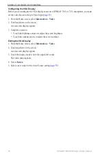
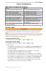
Page 63: ...receiver is turned off Any satellite signal strength bars shown are simulations and do not represent the strength of actual satellite signals Simulator mode turns the GPS receiver off for use indoors...

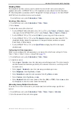
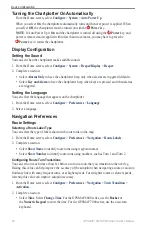
Page 64: ...age that appears on the chartplotter 1 From the Home screen select Configure Preferences Language 2 Select a language Navigation Preferences Route Settings Selecting a Route Label Type You can select...

Page 65: ...ueChart g2 Vision data card Safe Water Depth and Safe Obstacle Height CAUTION The Safe Depth and Safe Height settings influence how the chartplotter calculates an Auto Guidance line If an area has an...

Page 66: ...icient travel 6 Complete an action If the placement of the Auto Guidance line is satisfactory select Menu Navigation Options Stop Navigation Proceed to step 10 If the Auto Guidance line is too close t...

Page 67: ...rid to set grid north as the heading reference 000 Select User Mag Var to set the magnetic variation value manually For the GPSMAP 6000 series use the Rocker or the Numeric Keypad to enter the magneti...

Page 68: ...ect Configure Preferences Units System Units Custom 2 Complete an action Select Depth and select Feet Fathoms or Meters Select Temperature and select Fahrenheit or Celsius Select Distance and select M...

Page 69: ...in a different corner of the chart You can select the type of data that appears in each section of the data bar 1 From the Home screen select Charts 2 Select a chart or a 3D chart view 3 Select Menu D...

Page 70: ...Sailing Water speed wind speed wind angle and wind velocity made good Showing the Fishing Fuel or Sailing Data Bars The fishing fuel and sailing data bars appear in a row across the bottom of the cha...

Page 71: ...navigation data bar is on and you are navigating a route Showing the Compass Tape Data Bar The compass tape data bar appears in a row across the top of a chart or a 3D chart view above the navigation...

Page 72: ...lect Done Select Trails to show the tracks of AIS vessels Select the length of the track that appears using a trail Information about Your Boat Calibrating a Water Speed Device If you have a speed sen...

Page 73: ...far before arrival the alarm should sound in either minutes or a unit of distance For the GPSMAP 6000 series use the Rocker or the Numeric Keypad to enter the time or distance For the GPSMAP 7000 seri...

Page 74: ...g the GPS Accuracy Error Alarm You can set an alarm to sound when the GPS location accuracy falls outside the user defined value 1 From the Home screen select Configure Alarms System GPS Accuracy On 2...

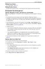
Page 75: ...w garmin com 1 Complete an action Copy the data from HomePort to the prepared memory card using an SD card reader attached to the computer according to the process described in the Transferring Data t...

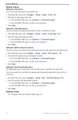
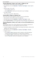
Page 76: ...a Transfer Card 3 Select Copy Built In Map to copy the maps loaded onto your chartplotter to the memory card Copying Waypoints Routes and Tracks to or from all Chartplotters on a Network You can trans...

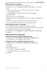
Page 77: ...and paste it to any location on the computer Restoring Backup Data to a Chartplotter 1 Insert a memory card into an SD card reader that is attached to the computer 2 Copy a backup file from the comput...

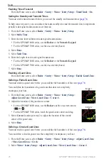
Page 78: ...after it warms up This gives you an opportunity to verify that the area around the radar is clear before beginning radar transmission 2 From the Home screen select Radar 3 Select Cruising Harbor Offsh...

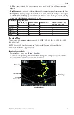
Page 79: ...e Radar GMR 20 21 40 41 GMR 18 18 HD 24 24 HD GMR 404 406 GMR 604 xHD 606 xHD 1204 xHD 1206 xHD Cruising x x x Harbor x Offshore x Dual Range x Sentry x x x x Cruising Mode Cruising mode is the standa...

Page 80: ...me transmission and disables any guard zones Showing Harbor Mode From the Home screen select Radar Harbor Harbor Mode Distance between rings Radar range Offshore Mode Offshore mode is the standard rad...

Page 81: ...es If you switch from Harbor mode or Offshore mode to Dual Range mode all MARPA targets are cancelled and you cannot acquire MARPA targets until you exit Dual Range mode Showing Dual Range Mode From t...

Page 82: ...ct Done Enabling a Guard Zone From the Home screen select Radar Sentry Menu Sentry Setup Enable Guard Zone Defining a Partial Guard Zone You must enable a guard zone before you can define the boundari...

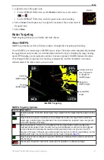
Page 83: ...racking MARPA target Lost MARPA target Dangerous MARPA target Closest point and time of approach to dangerous MARPA target MARPA Targeting Symbols Symbol Description Acquiring a target Concentric dash...

Page 84: ...Target Target options 4 Select Acquire Target Removing a MARPA Tag from a Target Object 1 From the Home screen select Radar 2 Select Cruising Harbor or Offshore 3 Complete an action For the GPSMAP 600...

Page 85: ...series 4 Select the type of threats to include in the list All Threats MARPA threats only or AIS threats only Showing AIS Vessels on the Radar Screen AIS requires the use of an external AIS device and...

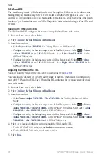
Page 86: ...u Show VRM EBL for the GPSMAP 6000 series Select Right Show VRM EBL for the GPSMAP 7000 series Adjusting the VRM and the EBL You must show the VRM and the EBL before you can adjust them page 80 You ca...

Page 87: ...ries 4 Complete an action For the GPSMAP 6000 series use the Rocker to adjust the diameter of the VRM and the angle of the EBL so that the intersection point of the VRM and EBL is at the target locati...

Page 88: ...llel to a Saved Route on the Radar Screen Before you can browse a list of routes and navigate to one of them you must record and save at least one route page 35 Navigation lines must be showing in ord...

Page 89: ...ar Overlay does not show data based on the Dual Range radar mode and settings configurations applied to the overlay are not applied to the Dual Range mode Radar Overlay on the Navigation Chart Radar O...

Page 90: ...r the Radar Overlay Note The Fishing chart is available with a preprogrammed BlueChart g2 Vision data card 1 From the Home screen select Radar Radar Overlay Menu Setup Chart Setup 2 Complete an action...

Page 91: ...t environmental conditions Selecting a Radar Range See Adjusting the Zoom Scale on the Radar Screen page 72 About Gain and Clutter The gain controls the sensitivity of the radar receiver The default s...

Page 92: ...te Depending upon the radar in use the gain setting configured for use in one radar mode may or may not be applied to other radar modes or to the Radar Overlay page 85 1 From the Home screen select Ra...

Page 93: ...r screen This image can obscure smaller targets located near it Note Depending upon the radar in use the gain setting configured for use in one radar mode may or may not be applied to other radar mode...

Page 94: ...ise Rejection Sea Clutter for Cruising Harbor Offshore or Sentry mode Configure the setting for the short range screen in Dual Range mode Select Menu Noise Rejection Sea Clutter for the GPSMAP 6000 se...

Page 95: ...rom the Home screen select Radar 2 Select Cruising Harbor Offshore Dual Range or Sentry mode 3 Complete an action Select Menu Noise Rejection FTC Off for Cruising Harbor Offshore or Sentry mode Config...

Page 96: ...ise Rejection FTC for the GPSMAP 6000 series Select Left Noise Rejection FTC for the GPSMAP 7000 series 4 Complete an action Select High Medium or Low to decrease or increase the appearance of rain cl...

Page 97: ...a glance information All data bars configured for use in one radar mode appear in every other radar mode All data bars configured for use on the Radar Overlay appear only on the Radar Overlay and must...

Page 98: ...ine Select Next Turn Distance to show next turn data based on distance Select Next Turn Time to show next turn data based on time Select Destination and select Distance Time to Destination or Arrival...

Page 99: ...le navigating 1 From the Home screen select Charts 2 Select Cruising Harbor or Offshore mode 3 Select Menu Radar Setup Data Bars Compass Tape On Radar Display Settings Setting the Radar Color Scheme Y...

Page 100: ...ar Radar Setup Appearance Heading Line Show Showing and Hiding Range Rings on the Radar Screen The range rings help you to visualize distances on the Radar screen This setting does not apply to the Ra...

Page 101: ...r screen 2 Select Angle 1 Adjust Move 3 Select Up or Down to adjust the size of the no transmit zone 4 Select Angle 2 Adjust Move 5 Select Up or Down to adjust the size of the no transmit zone Front o...

Page 102: ...Menu Waypoints Tracks Tracks On Managing Tracks See Tracks page 39 Selecting a Waypoint Label Type You can select the type of labels shown with waypoints on the Radar Overlay 1 From the Home screen s...

Page 103: ...the heading For the GPSMAP 7000 series use the on screen keyboard Select Done Select Trails to show the tracks of AIS vessels Select the length of the track that appears using a trail Radar Overlay N...

Page 104: ...e Showing and Configuring Navaid Symbols You can show and configure the appearance of navaid symbols on the Radar Overlay 1 From the Home screen select Charts Radar Overlay Menu Setup Chart Setup Symb...

Page 105: ...creen select Sonar Full Screen Full screen Sonar View Suspended target Bottom Depth temperature and water speed GPS speed and GPS heading Transducer frequency Range Setting the Zoom Level on the Full...

Page 106: ...er frequency Zoom level Zoom window Zoomed depth scale Split frequency Sonar View In the split frequency sonar view the left side of the screen shows a full view graph of 200 kHz frequency sonar data...

Page 107: ...g 1 From the Home screen select Sonar Temp Log 2 Select Menu 3 Complete an action Select Duration to set the time elapsed scale The default setting is 10 minutes Increasing the time elapsed scale allo...

Page 108: ...roll Fast Medium or Slow to set the scroll speed manually Select Auto to have the scroll speed automatically adjust to the water speed of your boat if you are using a water speed sensor or a speed cap...

Page 109: ...uring the Appearance of Suspended Targets You can set how the sonar interprets suspended targets 1 From the Home screen select Sonar Sonar Setup Appearance Fish Symbols 2 Complete an action Select to...

Page 110: ...nar Screen The Noise Rejection setting appears only when you have manually increased or decreased the gain setting page 104 You can minimize the appearance of weak sonar returns by increasing the nois...

Page 111: ...er the depth that triggers the shallow water alarm For the GPSMAP 6000 series use the Rocker or Numeric Keypad For the GPSMAP 7000 series use the on screen keyboard 4 Select Done 5 Select Deep Water O...

Page 112: ...n of the transducer If the transducer is installed at the water line measure the distance from the transducer location to the keel of the boat Enter this value in step 3 as a positive number If the tr...

Page 113: ...ture measured in step 1 from the water temperature measured in step 2 This is the temperature offset Enter this value in step 5 as a positive number if the sensor connected to the chartplotter measure...

Page 114: ...s you to quickly set up and send individual routine call details to your Garmin VHF radio page 113 X When you initiate a man overboard distress call from your radio the chartplotter shows the man over...

Page 115: ...istress call If position information was sent with the distress call that information is also available and recorded with the call The symbol designates a distress call in the DSC list and marks the p...

Page 116: ...S key for at least three seconds to send the distress call For information on placing distress calls from your radio see your Garmin VHF Radio Owner s Manual You can mark an MOB and navigate to it pag...

Page 117: ...Trail Line Select a color for the trail line Deleting a Position Report Call 1 From the Home screen select Information DSC List 2 Select a position report call 3 Select Review Clear Report Vessel Trai...

Page 118: ...screen select Charts 2 Select Navigation Chart Fishing Chart Perspective 3D or Mariner s Eye 3D 3 Select Menu Other Vessels DSC DSC List 4 Select a vessel 5 Select Review Edit Trail Show Changing the...

Page 119: ...mation 1 From the Home screen select Information DSC List 2 Select a vessel or a station to call 3 Select Review Call with Radio Send The chartplotter sends information about the call to the radio 4 O...

Page 120: ...012 6212 16 in 40 6 cm GPSMAP 7012 7212 25 in 63 5 cm GPSMAP 7015 7215 17 in 43 2 cm Hg Lamps inside this product contain mercury and must be recycled or disposed of according to local state or federa...

Page 121: ...ransfer the file to your computer Capturing Screenshots 1 Insert a memory card into the SD card slot on the front of the chartplotter 2 Select Configure System Beeper Display Screenshot Capture On 3 G...

Page 122: ...ormation Factory Settings Reset 2 Select Yes Communication with Wireless Devices Connecting a Wireless Device You can allow wireless devices such as a remote control or an optical mouse to communicate...

Page 123: ...and sonar NMEA 0183 input with support for the DPT depth or DBT MTW water temp and VHW water temp speed and heading sentences Configuring NMEA 0183 Output Sentences You can configure how the chartplo...

Page 124: ...A 0183 data is being sent across the system From the Home screen select Configure Communications NMEA 0183 Setup Diagnostics NMEA 2000 GPSMAP 6000 7000 series chartplotters are NMEA 2000 certified and...

Page 125: ...over the NMEA 2000 bus 1 From the Home screen select Configure Communications NMEA 2000 Setup Output Bridging 2 Complete an action Select On to enable output bridging from the chartplotter Select Auto...

Page 126: ...AGREEMENT PLEASE READ THIS AGREEMENT CAREFULLY Garmin Ltd and its subsidiaries Garmin grant you a limited license to use the software embedded in this device the Software in binary executable form in...

Page 127: ...zing 28 data fields 29 focus screen 30 functions 28 instrumentation data 30 layout 28 selecting 28 combinations data field adding 29 editing 30 removing 29 compass roses 14 compass tape data bar 65 93...

Page 128: ...98 lane width 20 language 3 58 large object interference 87 light sectors 13 M magnetic heading 11 93 magnetic variation 61 man overboard 5 34 35 Mariner s Eye 3D AIS 18 data bars 62 hazard colors 22...

Page 129: ...9 sailing data bar 64 92 satellite imagery 21 22 25 satellite signals 3 scale maximum 51 scale minimum 51 SD card slot 1 4 sea clutter 85 88 secure digital card 4 sentry mode guard zone 76 MARPA 75 ti...

Page 130: ...lit frequency view 100 split zoom view 100 spot depth soundings 12 98 surface radar 20 suspended targets 24 103 symbols 7 13 98 system information 115 T targeting 77 temperature log 101 tide stations...

Page 131: ......

Page 132: ...2010 Garmin Ltd or its subsidiaries Garmin International Inc 1200 East 151st Street Olathe Kansas 66062 USA Garmin Europe Ltd Liberty House Hounsdown Business Park Southampton Hampshire SO40 9LR UK Ga...

Reviews: