background image

APPENDIX A

93

ACCESSORIES & INSTALLATION (cont.)

Remote GPS Antenna

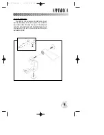
The GARMIN GA 27 remote GPS antenna can be used to enhance

satellite reception. Simply plug the “MCX” male connector on the end
of the GA 27 cable into the socket located on the side of the GPSMAP
195. Place the antenna in view of satellites, and the system is ready
for operation. The GA 27 can be mounted using a suction cup mount
(or, optionally, magnetic mount) which is included with the antenna.
You should ensure that the antenna’s location provides an unob-
structed view of much of the sky. This is critical to allow the antenna
to “see” at least the minimum four satellites needed to compute your
position and track your flight.

GA 27

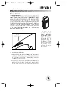
Suction Cup Mount

To use the suction cup mount:

1. Attach the suction cup mount to the bottom of the GA 27 antenna

using the two flat head screws (provided). Position the antenna as
low as possible on the windshield to maximize satellite visibility and
not obstruct your view of the sky.

2. The suction cup mount can be adjusted to compensate for aircraft

windshields of varying angles. The adjustment is made by rotating
the large suction cup until the proper angle for mounting is obtained.

The GARMIN GA 27

low-profile remote-mount
antenna is designed to be
used with several different
GARMIN GPS units. To use
this antenna with the
GPSMAP 195, simply plug
the right-angle “MCX” male
connector on the end of the
GA 27 cable into the socket
on the left side—near the
top  of the unit.

gps 195 manual C  7/1/99 4:49 PM  Page 93

Summary of Contents for GPSMAP 195

Page 1: ...GPSMAP 195 Pilot s Guide Reference gps 195 manual C 7 1 99 4 48 PM Page 1...

Page 2: ...gps 195 manual C 7 1 99 4 48 PM Page 2...

Page 3: ...ess prior written consent of GARMIN Corporation GARMIN hereby grants permission to down load a single copy of this manual and of any revision to this manual onto a hard drive or other electronic stora...

Page 4: ...harmful interference to radio communications Furthermore there is no guarantee that interference will not occur in a particular installation If this equipment does cause harmful interference the user...

Page 5: ...R RESULTING FROM THE USE MISUSE OR INABILITY TO USE THIS PRODUCT OR FROM DEFECTS IN THE PRODUCT SOME STATES DO NOT ALLOW THE EXCLUSION OF INCIDENTAL OR CONSEQUENTIAL DAMAGES SO THE ABOVE LIMITATIONS M...

Page 6: ...ays major thoroughfares optimized for 3000 through 20 nm scales and usable down to 1 10 nm Three dimensional controlled and special use airspace data with multiple airspace incursion warnings Built in...

Page 7: ...l Quick Reference Guide Optional Accessories PC Interface Cable Database Update uses PC Interface Cable Power Data Cable NiCad Battery Charger Kit PC Software Kit MCX to BNC Adapter for connection to...

Page 8: ...entire sections of text You may also wish to refer to this section for information about the more advanced features not covered in Section One How To Index The list below is provided to help you quick...

Page 9: ...ition Page and Options 49 50 Map Page Options and Using the Cursor 51 58 HSI Page and Options 59 61 Active Route Page and Options 62 63 Main Menu and Setup Menus 64 74 Routes Approaches and TracBack 7...

Page 10: ...LCD display Both the display and keypad may be illuminat ed for nighttime operation Information which appears on the display is referred to as a page A page can include graphics text or both The graph...

Page 11: ...formation from database or user waypoint from memory Press twice to capture your present position and save as a waypoint Returns display to a previous page or restores a data field s previous value Ad...

Page 12: ...can be changed from map data to map only and vice versa by pressing O selecting Data Fields Off On and pressing T Some keys can perform a variety of functions The O key is also used to display the op...

Page 13: ...pages To enter data you must first highlight using the R keypad the area on the display where it will be placed A rule of thumb to remember The data entry process begins and ends by pressing T The R k...

Page 14: ...e receiver at a comfortable height at arm s length from your body with the built in antenna the top part above the display parallel to the ground Your GPSMAP 195 calculates your position and movement...

Page 15: ...1 Press and hold the P key until the power tone sounds The welcome page will appear while the unit conducts a self test Once the internal test is complete the aviator s warning will appear asking you...

Page 16: ...for use The GARMIN GPSMAP 195 is a powerful electronic charting navigating system that provides detailed chart coverage and convenient control of many advanced features right from the moving map displ...

Page 17: ...R keypad 2 Decrease the screen contrast by pressing the left arrow of the R keypad 3 Press the T key to finish The GPSMAP 195 s three level screen backlighting is controlled with the P key and may be...

Page 18: ...the bar the stronger the signal For more information on the satellite status page turn to page 46 J RRR LLL Q The satellite status page is one of five main pages displayed on your GPSMAP 195 All five...

Page 19: ...r Q key repeatedly until the satellite status page is displayed 2 Press the Okey The options page will appear displaying a menu of options and functions for the status page 3 Use the UP or DOWN arrow...

Page 20: ...rby waypoints An on screen cursor lets you pan to other map areas determine the range and bearing to a position and perform various waypoint and route functions Note the on screen cursor as well as be...

Page 21: ...highway near your position Notice how another data field appears at the top of the page showing the bearing and distance from your aircraft to the cursor along with the lat long position of the curso...

Page 22: ...port Let s take a look at the clos est airports in your area To view the nine nearest airports 1 Press the N key to display the nearest waypoints page A list of the nine nearest airports appears along...

Page 23: ...t lets you start a TracBack route select a published approach for an airport or select a stored route to navigate After panning to a location on the map display pressing G allows you to graphically se...

Page 24: ...ad toward our airport by adjusting the ground speed and track to get a feel for how the HSI works To adjust the simulated aircraft ground speed 1 Press the UP arrow of the R keypad to increase the spe...

Page 25: ...tting represents the distance from the center of the CDI to full left or right limits The default CDI setting is 1 25 nm but can also be set for 0 25 or 5 0 nm ranges To change the CDI scale 1 Press t...

Page 26: ...ay have to wait a few min utes to get this message depending on how fast you are going NOTE The airspace alert occurs when your current altitude places you within the floor and ceiling limits of the a...

Page 27: ...e to intrusion if applicable 2 To view specific information on any listed airspace highlight the desired airspace name using the R keypad and press T The airspace definition page appears providing add...

Page 28: ...ypad and press T The track log page allows you to specify whether to record a track log and define how it is recorded A track log is a record of position samples showing where you have been This infor...

Page 29: ...elevation fuel services runways approaches and communications frequencies VORs Identifier city state country facility name position lat lon frequency and co located DME or TACAN availability NDBs Iden...

Page 30: ...elect the desired waypoint A list showing each duplicate by waypoint category and region makes it easy to identify the correct one To select the desired waypoint from a list of duplicates 1 With the d...

Page 31: ...and enter the desired airport identifier The airport page initially displayed will be the same as the last airport page viewed 2 Use the LEFT arrow to move the field highlight to the Loc Comm Rwy or A...

Page 32: ...location page Elevation Field elevation in feet or meters Position Airport location in the position format you have currently selected from the setup page e g latitude longitude or UTM UPS Fuel Lists...

Page 33: ...g information for the selected airport The runway area map provides a north up graphic of available runways with length width surface and lighting data listed below the runway designation The Surface...

Page 34: ...lighted the outline border becomes wider 2 Press Tto activate the panning function and use the Rkeypad to pan in the desired direction A cursor will appear and as it reaches the edge of the runway are...

Page 35: ...the panning function and use the Rkeypad to pan in the desired direction A cursor will appear and as it reaches the edge of the approach area map the map will scroll under the cursor 3 If you zoom in...

Page 36: ...pan in the desired direction A cursor will appear and as it reaches the edge of the VOR area map the map will scroll under the cursor 3 If you zoom in or out while panning the map will be recentered...

Page 37: ...last waypoint category available from the GPSMAP 195 s W key is user waypoints The user waypoint page allows entry of a desired waypoint by name identifier and displays the waypoint s position user co...

Page 38: ...Waypoint allows you to create a new waypoint using the user waypoint page To create a user waypoint 1 Highlight the Create Waypoint option and press T The user waypoint page appears with the waypoint...

Page 39: ...int press O select Delete Waypoint and press T A confirmation box appears Highlight Yes and press T to delete the waypoint 4 To delete all user waypoints from memory press O select Delete All User Wpt...

Page 40: ...O The W key is also used to save new waypoints using the GPSMAP 195 s AutoStore function AutoStore allows you to quickly store your present position and add the new waypoint to a selected route if des...

Page 41: ...create a waypoint at the panning cursor s position press T 4 To revert back to your present position and save it as a user way point highlight Use GPS Posn at the bottom of the page and press T twice...

Page 42: ...t Yes and press T A symbol waypoint may be selected as a destination waypoint by panning to the waypoint s location and pressing G To select a symbol waypoint as a GOTO destination 1 Highlight the des...

Page 43: ...for each airport also appears To view the nearest waypoints 1 Press the N key to display the nearest waypoint page 2 If an airspace alert was recently provided the GPSMAP 195 will default to the airsp...

Page 44: ...tion The nearest FSS ARTCC page displays the facility name bearing and distance from your pre sent position and the facility s frequency s To view the nearest FSS and ARTCC frequencies 1 Press the N k...

Page 45: ...is projected to enter the airspace If the air space is nearby less than 2 nm but you are not projected to enter it the time to entry is replaced by Near If you are already inside the airspace Inside i...

Page 46: ...oint name using the R keypad and press T 4 With GOTO highlighted press T The GOTO window is also used to cancel the current GOTO destination When cancelled the GPSMAP 195 will resume navigation using...

Page 47: ...After you ve already pressed G To select a menu option 1 Highlight the desired option and press T The following options are available Select Route allows you to quickly select a stored route one that...

Page 48: ...ill give you an idea of what the receiver is doing at any given moment The sky view and signal strength bars give you an indication of what satellites are in view and whether or not they are being rec...

Page 49: ...n appears on every page when using battery power It s not necessary to return to the status page to see battery condition The status field will show one of the following conditions Searching the Sky t...

Page 50: ...ext See page 13 for instructions on graphic initialization To initialize your position by text entry 1 Highlight the Initialize Position option and press T The map display appears so that you can grap...

Page 51: ...moving and four user selectable data fields ground track TRK ground speed SPD distance traveled TRP and altitude ALT The bottom half of the page displays coordinates for your present position along wi...

Page 52: ...n and press T The following options are available Reset Trip Distance resets the trip odometer TRP field to zero Change Data Fields allows you to choose the data dis played in the four user selectable...

Page 53: ...d Each data field may be configured to display any one of fourteen data options The data window may also be changed to display additional data fields a graphic compass or a CDI scale The status bar at...

Page 54: ...r will be displayed in the data window along with the cursor s position coordinates Keep in mind that when the cursor is stationary the distance and bearing from your present position will change as y...

Page 55: ...ypoints are loca tions identified on the map by any one of thirty five waypoint sym bols but do not have a waypoint name The GPSMAP 195 stores up to 250 symbol waypoints see page 39 for more informati...

Page 56: ...e internal base map and a mapping datacard map detail will be displayed using the data with the best resolution When the selected zoom range exceeds the resolution of the available chart data overzoom...

Page 57: ...data displayed in each data field at the top of the map page Definitions for unfamiliar terms may be found in Appendix F The following options are available BRG bearing to active destination waypoint...

Page 58: ...500 through each lower scale stopping at 2 as you approach your destination waypoint To turn latitude longitude gridlines on or off 1 Highlight the Setup Map Features option and press T 2 Highlight t...

Page 59: ...s T 3 Select On or Off and press T To display airports and change their fonts 1 Highlight the Setup Aviation Data option and press T 2 Highlight an Airports text field and press T Large airports are t...

Page 60: ...ter understanding of how these setup features are used Measure BRG DIS allows you to measure the bearing and distance between any two points on the map display To measure the BRG DIS between two point...

Page 61: ...will rotate to indicate your current ground track at the top of the page The desired track pointer points in the direction of the desired course to your destination waypoint and will rotate with the c...

Page 62: ...ss T The OBS data field bottom left of HSI display will present an OBS heading 2 Select the desired OBS course using the LEFT and RIGHT arrows of the Rkeypad and press T The D bar on the CDI will now...

Page 63: ...a GOTO or route must be in use and a valid VNAV profile must be entered on the vertical navigation submenu See page 84 for more information on VNAV Cancel Capture is used to return the VNAV indicator...

Page 64: ...s you navigate a route the waypoint list will automatically update to indicate the next active to waypoint using this arrow icon From the active route page you can Change the route comment see page 76...

Page 65: ...the new active leg This feature is handy if you stray well off course and later wish to return to the route Invert Route reactivates the active route in reverse order and begins navigation Deactivate...

Page 66: ...e divided into categories by function system setup route track timer features and navigation planning features To select a submenu from the main menu page 1 Highlight the submenu you want to view and...

Page 67: ...the datum reference used to determine where your position is Nearest Airport Criteria is used to set minimum surface conditions and minimum runway lengths when viewing the nearest airport list Beeper...

Page 68: ...r Track is selected press T enter the desired ground track and press T again Auto Trac will automatically adjust the ground track based upon the bearing to an active GOTO or route waypoint 3 Highlight...

Page 69: ...3 If enabling the alarm highlight the distance field and press T Enter the alarm distance and press T If you deviate beyond the alarm distance left or right of course a CDI Alarm message occurs The la...

Page 70: ...still be displayed on the map page unless that category is turned off from the map options page To turn an airspace alarm on or off 1 Highlight the desired airspace category and press T 2 Select On or...

Page 71: ...er Mag Var setting is provided for circumstances where Auto Mag Var may not provide the correct magnetic variation Be advised that if you select User Mag Var and enter a value this value does not chan...

Page 72: ...sure setting 1 Highlight the desired field and press T 2 Select the desired units and press T The graphic CDI that is part of the HSI page may be configured to scale distances of 0 25 1 25 or 5 00 uni...

Page 73: ...id UTM UPS Universal Transverse Mercator and Universal Polar Stereographic grids To change the position format 1 Highlight the Position Format field and press T 2 Select the desired position format an...

Page 74: ...nimum runway length is zero To enter a minimum runway length 1 Highlight the Minimum Runway Length field and press T 2 Enter the desired minimum and press T The beeper display battery submenu provides...

Page 75: ...rent time using a 12 or 24 hour clock This field is also used to select between local or UTC time To select the desired time format 1 Highlight the Time Format field and press T 2 Select the desired s...

Page 76: ...ovides NMEA 0183 output See Appendix B for additional NMEA sentence information NMEA In No Out allows input from a NMEA compatible exter nal device with no output capabilities No In NMEA Out provides...

Page 77: ...view the route list page 1 Highlight Routes from the main menu and press T Routes can be created and modified from the route edit page allowing you to enter the identifier for each waypoint along the...

Page 78: ...1 Highlight the Review option and press T To remove a route waypoint 1 Highlight the Remove option and press T To insert a new waypoint before the selected route waypoint 1 Highlight the Insert optio...

Page 79: ...e Route activates the highlighted route and begins navigation Invert Route activates the highlighted route in reverse order and begins navigation Deactivate Route stops navigation of the route current...

Page 80: ...l to copy a TracBack route route 0 to another route to prevent losing the route the next time a TracBack route is activated To copy a route 1 Highlight the Copy Route option and press T The selected r...

Page 81: ...first point in the approach and automatically sequence through each point in the approach to the missed approach point MAP If you re currently navigating a route instead of using the GOTO function se...

Page 82: ...cord ed wrapping through the available memory and replac ing the oldest track data with new data Interval defines the frequency with which the track plot is recorded Three interval settings are availa...

Page 83: ...key twice to display the main menu page 2 Highlight the Track option and press T 3 Select the Delete Track option and press T 4 Highlight the Yes field and press T 5 Verify that the Record Mode field...

Page 84: ...ur track log are very complex 30 waypoints may not accurately mark your exact path The receiver will then assign the 30 waypoints to the most significant points of your track and simplify segments wit...

Page 85: ...a continuous count up timer which automatically stops when using external power When depleted batteries are replaced with a fresh set the GPSMAP 195 will automatically reset the timer to zero You can...

Page 86: ...r MSL as desired and press T Above waypoint will use the altitude of a destination airport as stored in the internal Jeppesen database MSL lets you set a specific target altitude for any waypoint type...

Page 87: ...At one minute before you reach the initial descent point a message Approaching VNAV Profile occurs The estimated time to VNAV profile ETV will sequence from indicating time to initial descent point t...

Page 88: ...ting 7 Enter the barometric pressure and press T 8 Press T to begin entry of the total air temperature TAT 9 Enter the TAT and press the T key The calculated density alti tude and true airspeed will b...

Page 89: ...d and use the R keypad to enter the name of the starting waypoint You may leave the waypoint field blank to use your present position or press the O key to select the waypoint from the waypoint list o...

Page 90: ...me whichever you have selected and press T The bottom of the page will now display the planning information for the route leg selected or the cumulative values for the entire route The route planning...

Page 91: ...ons to verify the weight and balance conditions for your aircraft By entering the weight and arm value on this page the GPSMAP 195 can calculate the total weight moment and center of gravity CG figure...

Page 92: ...90 gps 195 manual C 7 1 99 4 49 PM Page 90...

Page 93: ...rol yoke of an aircraft for easy access without blocking the view of the instrument panel The clamp that comes with the standard yoke mount is configured to fit the control yoke of more than 90 of gen...

Page 94: ...the clamp adjustment knob The yoke mount includes a mounting bracket which is used to secure the GPSMAP 195 during flight Using the Mounting Bracket To secure the GPSMAP 195 using the mounting bracket...

Page 95: ...ur position and track your flight GA 27 Suction Cup Mount To use the suction cup mount 1 Attach the suction cup mount to the bottom of the GA 27 antenna using the two flat head screws provided Positio...

Page 96: ...e the batteries observing the polarity diagram engraved in the lid 3 Match the two tabs on the lid with the slots in the base of the pack The lid will snap into place PRESS NiCad Battery Pack A NiCad...

Page 97: ...message try removing the card and reinserting it If the card is still not recognized contact the dealer you purchased it from for assistance Datacards are not waterproof should not be exposed to moist...

Page 98: ...the range field will display Ovr Zm This warning indicates that although the information is still being displayed you should exercise extreme caution using the data When a datacard is installed the G...

Page 99: ...screw holes and secure the adapter using either the long thumb screws supplied or standard M3 x 5 6mm machine screws To use this adapter with the yoke mount insert the adapter connector through the s...

Page 100: ...pted in RTCM 104 v 2 0 format through the NMEA In BROWN harness lead The GARMIN GBR 21 is the recommended beacon receiver for use with the GPSMAP sys tem Other receivers with the correct RTCM format m...

Page 101: ...old Approx 5 minutes AutoLocate Approx 5 minutes Search the sky Update Rate 1 second continuous Position Accuracy 1 5 meters 3 16 ft 15 meters 49 ft RMS Velocity Accuracy 0 1 knot RMS steady state Dyn...

Page 102: ...n authorized GARMIN service center immediately Degraded Accuracy The accuracy of the GPSMAP 195 has been degraded beyond 500 meters due to poor satellite geometry or data quality You should check othe...

Page 103: ...n deleted from the route RTCM Input has Failed DGPS data being received has been lost You are no longer receiving the beacon signal Searching the Sky The GPSMAP 195 is in search ing the sky for almana...

Page 104: ...ght Service Station FT Feet FT Full Time GL Gallons GND Ground GPS Global Positioning System GR Glide Ratio GRT Glide ratio to Target GS Ground Speed HDG Heading HG Inches of Mercury IALT Indicated Al...

Page 105: ...ndard Instrument Departure SLCT Select SPD Ground Speed SRFC Surface STAR Standard Terminal Arrival Route STR Steer To TACAN Tactical Air Navigational Aid TAS True Airspeed TAT Total Air Temperature T...

Page 106: ...a 6 1 glide ratio indicates a 1000 vertical descent for every 6000 horizontal distance travelled Glide Ratio To Target GRT The glide ratio required to descend from present position and altitude to the...

Page 107: ...illustrates some of the basic navigation terms used with the GPSMAP 195 V N A V P R O F I L E GLIDE RATIO TO TARGET DISTANCE TO TARGET DISTANCE TO PROFILE TARGET ALTITUDE AIRPORT The diagram below ill...

Page 108: ...rd Finland Hayford Finland Gandajika Base Gandajika Base Republic of Maldives Geod Datm 49 Geodetic Datum 49 New Zealand Guam 1963 Guam 1963 Guam Island Gux 1 Astro Gux 1 Astro Guadalcanal Island Hjor...

Page 109: ...Grt Britn England Isle of Man Scotland Shetland Isl Wales Pico De Las Nv Canary Islands Ptcairn Ast 67 Pitcairn Astro 67 Pitcairn Isl Prov S Am 56 Prov So Amricn 56 Bolivia Chile Colombia Ecuador Guya...

Page 110: ...iation Indicator CDI 55 59 70 Course To Steer CTS 55 61 102 104 Course Made Good CMG 102 Crosstrack Error XTK 55 61 104 Cursor Mode 51 Cursor Movement 19 51 53 D Database 4 27 74 Data Field Entry 10 1...

Page 111: ...Airspace 43 Nearest ARTCC 42 Nearest FSS 42 Nearest Waypoint Page 20 41 42 NMEA Output Formats 98 NMEA Setup 74 O Omni Bearing Selector OBS 60 Output Setup 74 Overzoom 19 96 P Packing List 5 Page Seq...

Page 112: ...el Planning 87 89 Trip Odometer 49 50 Turn TRN 55 61 102 104 U Unit Settings 69 70 Units of Measure 70 User Waypoint Information 35 36 V Vertical Speed to Target VST 55 102 104 VNAV 84 85 VOR Informat...

Page 113: ...gps 195 manual C 7 1 99 4 49 PM Page 111...

Page 114: ...KS 66062 USA GARMIN Europe LTD Unit 5 The Quadrangle Abbey Park Industrial Estate Romsey SO51 9AQ UK GARMIN Asia Corp 3F No 1 Lane 45 Pao Hsing Road Hsin Tien Taipei Taiwan R O C Web Site Address www...

Reviews: