background image

16

GPSMAP 4000/5000 Series Installation Instructions

Advanced nMEA 0183 Wiring

The GPSMAP 4000/5000 series chartplotter features four ports to receive NMEA 0183 data (RX ports), and two ports to send NMEA 0183 data 

(TX ports). Wire one NMEA 0183 device per RX port to send data to a 4000/5000 series chartplotter. Wire up to three NMEA 0183 devices in 

parallel to each TX port to receive data from a 4000/5000 series chartplotter.
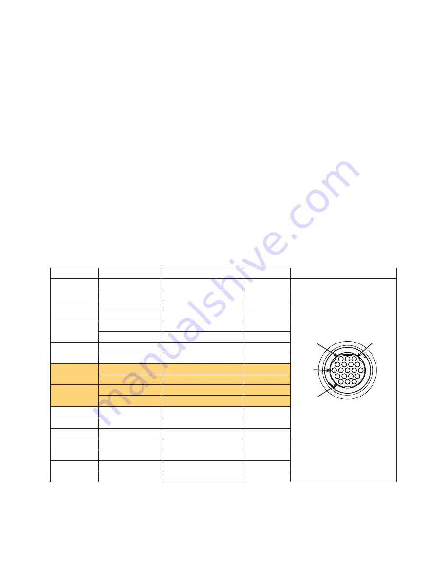
Each RX and TX port has 2 wires, labeled A (+) and B (-) according to the NMEA 0183 convention. Connect the corresponding A (+) and B (-) 

wires of each port to the A (+) and B (-) wires of your NMEA 0183-compliant device. Refer to the table and wiring diagrams when wiring the 

4000/5000 chartplotter to NMEA 0183 devices.

Consult the installation instructions of your NMEA 0183-compliant device to identify the Transfer (TX) A(+) and B(-) wires and 

Receiving (RX) A(+) and B(-) wires.

 Use 28 AWG, shielded, twisted-pair wiring for extended runs of wire. Solder all connections and seal 

them with heat-shrink tubing.

notes:

•  For two-way communication with a NMEA 0183 device, the ports on the GPSMAP 4000/5000 chartplotters are not linked. For example, 

if the RX port of the NMEA 0183-compliant device is wired to TX port 1 on the GPSMAP 4000/5000, you can wire the TX port of your 

NMEA 0183-compliant device to RX port 1, port 2, port 3, or port 4 on the GPSMAP 4000/5000.

•  The ground wires on the NMEA 0183 data cable from the GPSMAP 4000/5000 series chartplotter and your NMEA 0183-compliant device 

must both be grounded.

•  Approved NMEA 0183 sentences—GPBWC, GPRMC, GPGGA, GPGSA, GPGSV, GPGLL, GPBOD, GPRMB, GPRTE, GPVTG, 

GPWPL, GPXTE, and Garmin proprietary sentences —PGRME, PGRMM, and PGRMZ.

•  The GPSMAP 4000/5000 series chartplotter also includes support for the WPL sentence, DSC, and sonar NMEA 0183 input with support for 

the DPT (depth) or DBT, MTW (water temperature), and VHW (water temperature, speed, and heading) sentences.

•  Use the Communications section of the Configure menu on the GPSMAP 4000/5000 series chartplotter to set up NMEA 0183 

communications. See the owner’s manual for details.

Port

Wire Function

Wire Color

Pin number

Connector

Receiving Port 1

RX / A (+)

White

1

RX / B (-)

Orange/White

2

Receiving Port 2

RX / A (+)

Brown

5

RX / B (-)

Brown/White

6

Receiving Port 3

RX / A (+)

Violet

9

RX / B (-)

Violet/White

10

Receiving Port 4

RX / A (+)

Black/White

11

rX / B (-)

Red/White

12

Transmitting 

Port 1

tX / A (+)

Gray

3

tX / B (-)

Pink

4

Transmitting 

Port 2

tX / A (+)

Blue

7

tX / B (-)

Blue/White

8

N/A

GPS 17 in

Green/White

13

N/A

GPS 17 out

Green

14

N/A

spare

15

N/A

Alarm

Yellow

16

N/A

Accessory on

Orange

17

N/A

Ground

Black

18

N/a

spare

19

GPSMAP 4000/5000 Series nMEA 0183 Data Cable

NMEA 0183 Cable End 

View

PIn 1

PIn 3

PIn 8

PIn 17

Summary of Contents for GPSMAP 5215

Page 1: ...00 5000 series chartplotter confirm that the package contains the items listed on the box If any parts are missing contact your Garmin dealer immediately Warning See the Important Safety and Product I...

Page 2: ...securely attaches it to your specific mounting surface The size of the drill bit required depends on the mounting hardware chosen To install the bail mount bracket NOTE You cannot bail mount the GPSM...

Page 3: ...more of the four pilot holes inside the corner of the template to begin cutting the mounting surface 4 Using the jigsaw cut the mounting surface along the inside of the solid line indicated on the flu...

Page 4: ...tes Make sure the surface on which you mount the chartplotter has at least 7 in 18 cm of open space behind it to fit the chartplotter and the connected wires and make sure to leave approximately 1 2 i...

Page 5: ...into place Mounting the GPS 17x Antenna notice Be sure to follow the correct mounting directions and the correct wiring directions for the antenna included with your chartplotter You can surface mount...

Page 6: ...network Mounting the Antenna on a Pole Using the pole mount bracket you can install the antenna on a standard marine pole Mount not included A standard threaded marine pole mount has the following cha...

Page 7: ...e not appropriate for the surface you must supply the correct length of M4 screws to avoid damage to the top of the mounting surface The antenna can be mounted under a fiberglass surface Because the a...

Page 8: ...the grommet into the installation hole until it is seated Apply marine sealant as needed to weatherproof the cable Installing Locking Rings on the Cables To help make the cable routing process easier...

Page 9: ...g the Power Cable The GPSMAP 4000 5000 series chartplotter must be connected to the power supply for the boat Use the 2 pin power cable included and connect the power red and ground black wires notes...

Page 10: ...long enough you can add a drop cable extension up to 13 ft 4 m If more cable is needed add an extension to your NMEA 2000 backbone based on the NMEA 2000 guidelines 5 Disconnect one side of a NMEA 200...

Page 11: ...4 Connect the NMEA 2000 power cable to the top of one of the T connectors 5 Route and connect the included NMEA 2000 drop cables from the GPS 17x and from the GPSMAP 4000 5000 series chartplotter to t...

Page 12: ...r GSD sounder or GDL XM Weather receiver to any chartplotter on the network or to an optional GMS 10 Network Port Expander Data is shared between all chartplotters on the network BlueChart g2 Vision c...

Page 13: ...hartplotter Garmin GPSMAP 4000 5000 series chartplotter Garmin marine radar GSD 22 sounder unit To transducer GDL 30 30A XM weather unit NOTES Every device connected to the Garmin Marine Network must...

Page 14: ...as three network ports and acts as a port expander Wire the GPS antenna and additional NMEA devices to either the existing GPSMAP 3000 series chartplotter or the new GPSMAP 4000 5000 Series chartplott...

Page 15: ...ire color Wire Red power Black pwr gnd Red power Fuse 7 5 A 42 V Black data GND White orange white Gray Transmit A transmit B Receive A Black pwr gnd Black data GND Power cable NMEA 0183 Cable Wiring...

Page 16: ...0 you can wire the TX port of your NMEA 0183 compliant device to RX port 1 port 2 port 3 or port 4 on the GPSMAP 4000 5000 The ground wires on the NMEA 0183 data cable from the GPSMAP 4000 5000 series...

Page 17: ...er Fuse 7 5 A 42 V Black data GND RX A RX B TX A TX B tX A tX B rX A rX B Black pwr gnd Black data GND Power cable NMEA 0183 Cable OR OR Wiring to Send Data to a NMEA 0183 compliant Device With a Sing...

Page 18: ...a lamp a horn or both Garmin GPSMAP 4000 5000 series chartplotter Wire Color Red power Black gnd Yellow alarm Battery 10 35 Vdc Relay 100 ma max coil current Horn Lamp Fuse 7 5 A 42 V Power cable NMEA...

Page 19: ...Line composite video sources and PC monitor output 4008 4208 4010 4210 5008 5208 VGA output 4012 4212 5012 5212 5015 5215 XGA output Marine Video inputs are only available on the chartplotter to whic...

Page 20: ...ns After the cable is seated turn the locking ring clockwise until it stops To attach a Garmin Marine Network cable or a NMEA 2000 Micro connector cable carefully press the cable into the correct port...

Page 21: ...6 11 32 in H 8 7 16 in W 161 4 214 2 mm 4012 4212 7 19 64 in H 9 11 16 in W 184 3 245 8 mm 5008 5208 5 in H 6 47 64 in W 128 2 170 9 mm 5012 5212 7 7 64 in H 9 19 64 in W 180 49 235 97 mm 5015 5215 8...

Page 22: ...mation 127250 Vessel Heading 127250 Vessel Heading 128259 Speed Water Referenced 127489 Engine Parameters Dynamic 128267 Water Depth 127488 Engine Parameters Rapid Update 129025 Position Rapid Update...

Page 23: ...23 GPSMAP 4000 5000 Series Installation Instructions...

Page 24: ...ite at www garmin com 2011 Garmin Ltd or its subsidiaries Garmin International Inc 1200 East 151st Street Olathe Kansas 66062 USA Garmin Europe Ltd Liberty House Hounsdown Business Park Southampton Ha...

Reviews: