background image

20

GPSMAP

® 

585 Plus

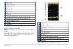
Interference

Adjusts the sensitivity to reduce the effects of interference from nearby 

sources of noise. The lowest interference setting that achieves the desired 

improvement should be used to remove interference from the screen. 

Correcting installation issues that cause noise is the best way to eliminate 

interference.

Interference Setting

Off


Low


Medium


High

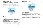
Interference from other acoustic equipment operating nearby or other 

electronic equipment on your boat may appear on the display as shown in 

the figures below. You may reduce the effect with a noise limiter. There are 

varying degrees of interference. Minor interference or noise can be stray 

signals that can look like actual targets. Severe noise can completely fill the 

screen and make depth readings impossible. To counter interference, you 

have to first identify the type of interference. Although most noises can be 

eliminated with fairly simple techniques, some interferences can only be 

reduced to a more acceptable level.

1. Sonar Cross-Talk interference

: caused by nearby fishfinder(s) of similar 

transmit frequency. It will appear as the diagonal lines across the screen. 

When two fishfinder’s transducer cones intersect, the units will not be able 

to tell the signals apart. See figure (A) below.

2. Electromagnetic Interference (EMI)

: caused by powerful electromagnetic 

waves radiated from electric equipment and wirings. The electromagnetic 

waves are then absorbed by the transducer cable and appear as vertical 

lines on the screen. See figure (B) below.

(A) Interference from other sonar

(B) Electrical interference

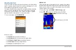
Surface Noise

When the sea is rough or the ship passes over a wave, surface noise may 

appear at the top of the screen. It can be suppressed with the CLUTTER 

function which hides surface noise to help reduce clutter. Wider beam widths 

(lower frequencies) can show more targets, but can generate more surface 

noise.

Surface noise

Summary of Contents for GPSmap 585 Plus

Page 1: ...Owner s Manual...

Page 2: ...organization of such changes or improvements Go to www garmin com for current updates and supplemental information concerning the use of this product Garmin GPSMAP Ultrascroll and the Garmin logo are...

Page 3: ...g the Display Colors 4 Setting the Beeper 5 GPS Satellite Signal Acquisition 5 Home Screen 5 Customizing the Home Screen 5 Adding a New Layout to the Home Screen 6 Page Shortcuts 6 Editing the Page Sh...

Page 4: ...e Settings 18 Advanced Sonar Settings 19 Interference 20 Surface Noise 20 Color Gain 21 TVG 21 Overlay Numbers Settings 21 Compass 22 Depth and Water Temperature Graphs 22 Charts and 3D Chart Views 22...

Page 5: ...34 Creating and Navigating a Route Using the Waypoint Map 34 Creating and Navigating a Route Using the Waypoint Map 35 Creating and Navigating a Route Using the Waypoint List 35 Editing a Saved Route...

Page 6: ...ssel in Distress 44 Position Tracking 44 Viewing a Position Report 44 Navigating to a Tracked Vessel 45 Creating a Waypoint at the Position of a Tracked Vessel 45 Editing Information in a Position Rep...

Page 7: ...ettings 53 Communications Settings 53 NMEA 0183 Settings 53 Navigation Settings 54 Restoring the Factory Default Settings 54 Appendix 55 Registering Your Device 55 Sun Cover 55 GPSMAP 585 Plus Specifi...

Page 8: ...vi GPSMAP 585 Plus...

Page 9: ...box for product warnings and other important information GPSMAP 585 Plus Dimensions Connector Descriptions 1 Power NMEA0183 Data Cable Connector 2 8 pins Transducer Cable Connector 3 BNC External GPS...

Page 10: ...select to adjust the gain From a sonar screen hold to open the clutter menu RANGE ZOOM From a sonar screen select to adjust the sonar range From a sonar screen hold to open the zoom menu Select to sc...

Page 11: ...structions 4 Wait several minutes while the software update process completes 5 When prompted leave the memory card in place and restart the chartplotter manually 6 Remove the memory card NOTE If the...

Page 12: ...ect Day Colors To use a dark background select Night Colors TIP You can configure the night color mode Select Configure Colors and select an option To allow the device to display day or night colors a...

Page 13: ...stion mark appears over on the screen For more information about GPS go to www garmin com aboutGPS Home Screen The home screen provides access to all of the features in the device The features are dep...

Page 14: ...ct Highway Overlay Numbers Overlay Numbers To turn on and off the compass tape data bar select Highway Overlay Numbers Overlay Numbers Compass Tape 4 Select Next 5 Enter a name for the layout TIP Sele...

Page 15: ...Numbers or Trip screens you must add them to the home screen 1 Select Customize Home Add Navigation Info 2 Select Numbers or Trip Numbers To customize the Numbers screen select Numbers MENU Change Num...

Page 16: ...ields require you to be navigating or require a connection to sensors to display data For example a temperature sensor must be connected to the chartplotter to display the temperature data field The d...

Page 17: ...eive Garmin ClearV scanning sonar you need a compatible transducer Garmin ClearV high frequency scanning sonar provides a detailed picture of the fishing environment around the boat in a detailed repr...

Page 18: ...tion because it puts more energy onto the target than traditional sonars Instead of sending just one single frequency CHIRP sonar sends a continuous sweep of frequencies ranging from low to high Garmi...

Page 19: ...hich the sonar is focused This allows you to zoom in a higher resolution in the focused depth When using shift bottom tracking may not work effectively because the sonar looks for data within the dept...

Page 20: ...a sonar screen select RANGE ZOOM 2 Select an option Select No Zoom to not use the zoom feature Select Bottom Lock to lock the screen to the water bottom Select Manual or Digital Zoom to manually set t...

Page 21: ...e Shift Zoom mode the fishfinder CPU only processes the sonar signals received from the selected depth range You can set the zoom manually 1 From a sonar screen select RANGE ZOOM Shift Zoom 2 Select o...

Page 22: ...Present Location 1 Pause the sonar 2 Select an option To create a mark at the cursor select MARK WPT To create a waypoint at the cursor hold MARK WPT To create a mark at your boat position with the cu...

Page 23: ...for detecting schools of fish at the bottom on the edges 200 kHz The higher the frequency the narrower the beam and the higher the resolution The 200 kHz frequency is ideal for detailed observations N...

Page 24: ...the Gain reduces screen clutter This can be corrected by gradually increasing the volume on the Gain control setting until more details appear on the display screen If the Gain control is set too high...

Page 25: ...a drop off or cliff manually adjusting the range allows a view of a specified depth range The bottom is shown on the screen as long as the bottom is anywhere within the manual range established 1 From...

Page 26: ...option To adjust the scroll speed automatically using speed over ground select Auto The Auto setting selects a scroll rate to match the boat speed so targets in the water are drawn with the correct as...

Page 27: ...rom the screen Turning On the A Scope NOTE This feature is not available in all sonar views The a scope is a vertical flasher along the right side of the full screen sonar view This feature expands th...

Page 28: ...of interference Although most noises can be eliminated with fairly simple techniques some interferences can only be reduced to a more acceptable level 1 Sonar Cross Talk interference caused by nearby...

Page 29: ...s from nearby objects and then ramping up the gain level over time as the ping travels into deeper water attenuating as it goes Adjusts the appearance of returns to compensate for weakened sonar signa...

Page 30: ...you can view the depth data graph page or temperature graph page you must add the page to your home screen page 5 Select Depth Data Graph or Temperature Data Graph Charts and 3D Chart Views The charts...

Page 31: ...d view of the bottom contours and depth soundings on the chart This chart removes navigational data from the chart provides detailed bathymetric data and enhances bottom contours for depth recognition...

Page 32: ...avoid land shallow water and other dangerous objects NOTE The offshore Fishing chart is available with premium charts in some areas NOTE Auto Guidance is available with premium charts in some areas 1...

Page 33: ...ts the appearance of the different charts and 3D chart views Marks Waypoints and Tracks on the Charts and Chart Views From a chart or a 3D chart view select MENU Marks Waypoints Tracks Tracks Shows tr...

Page 34: ...ppears using a trail Vessel Outline Shows the outline of AIS vessels Navigation and Fishing Chart Setup NOTE Not all settings apply to all charts and 3D chart views Some settings require external acce...

Page 35: ...nd network configuration Showing a Navigation Inset You can control whether a navigation inset appears on some chart views The navigation inset is shown only when the boat is navigating to a destinati...

Page 36: ...ting affects only the appearance of hazard colors for the Mariner s Eye 3D chart view It does not affect the safe water depth Auto Guidance setting or the sonar shallow water alarm setting Range Rings...

Page 37: ...ata onto a 2 GB memory card When you record data on a memory card in your chartplotter the new data is added to your existing Garmin Quickdraw Contours map and is saved on the memory card When you ins...

Page 38: ...Recording Offset Sets the difference between the sonar depth and the contour recording depth If the water level has changed since your last recording adjust this setting so the recording depth is the...

Page 39: ...n also download maps other users have created To access the Garmin Quickdraw Community sign in to your Garmin Connect account and then you can upload and download maps using a memory card Accessing th...

Page 40: ...emory card in the chartplotter The chartplotter automatically recognizes the contours maps The chartplotter may take a few minutes to load the maps Waypoints and Marks Waypoints are locations you reco...

Page 41: ...ypoint 4 Select an option To add a name select Name and enter a name To change the symbol select Symbol To change the depth select Depth To change the water temperature select Water Temp To change the...

Page 42: ...otters installed on your boat You must turn on user data sharing for both devices to share data Select User Data Manage Data User Data Sharing On on both devices User Data Settings Select User Data Ma...

Page 43: ...lect an option Creating and Navigating a Route Using the Waypoint List 1 Select User Data Routes Auto Guidance Paths New Route Using Waypoint List 2 Select waypoints 3 Select BACK Navigate To Editing...

Page 44: ...follow the purple line corrected course to go to your destination or steer back to the magenta line direct course Deleting a Saved Route 1 Select User Data Routes Auto Guidance Paths 2 Select a route...

Page 45: ...es you to identify and track other vessels and alerts you to area traffic When connected to an external AIS device the chartplotter can show some AIS information about other vessels that are within ra...

Page 46: ...Screen You can configure how other vessels appear on the AIS Radar screen 1 From the AIS Radar screen select MENU AIS Display Setup 2 Select an option To set the maximum distance of AIS vessels to dis...

Page 47: ...zone For example to be notified of a pending intersection 10 minutes before it will likely occur set Time To to 10 and the alarm will sound 10 minutes before the vessel intersects the safe zone A mes...

Page 48: ...dar screen Bearing Ring Shows a bearing relative to your heading or based on a north reference to help you determine the bearing to an object shown on the AIS Radar screen Nav Lines Shows the navigati...

Page 49: ...Select BACK Auto Guidance CAUTION The Auto Guidance feature is based on electronic chart information That data does not ensure obstacle and bottom clearance Carefully compare the course to all visual...

Page 50: ...this setting while navigating The available values for this setting are relative not absolute To ensure that the Auto Guidance line is placed the appropriate distance from shore you can assess the pla...

Page 51: ...o Guidance line is satisfactory select MENU Stop Navigation and proceed to step 10 If the Auto Guidance line is too close to known obstacles select Settings Navigation Auto Guidance Shoreline Distance...

Page 52: ...DSC list You can make calls to a DSC contact from the chartplotter 1 Select Navigation Info Other Vessels DSC List Add Contact 2 Enter the Maritime Mobile Service Identity MMSI of the vessel 3 Enter t...

Page 53: ...Select Navigation Info Other Vessels DSC List 2 Select a position report call 3 Select Edit Clear Report Viewing Vessel Trails on the Chart You can view trails for all tracked vessels on some chart vi...

Page 54: ...king an Individual Routine Call to an AIS Target 1 From a chart or 3D chart view select an AIS target 2 Select AIS Vessel Call With Radio 3 If necessary select Channel and select a new channel 4 Selec...

Page 55: ...urrents Lunar Calendar Device Configuration GPSMAP 585 Plus Settings Menu Tree System Display Backlight Color Mode Configure Colors Beeper GPS Skyview GPS Mode SBAS Speed Filter Auto Power Off On Lang...

Page 56: ...or Drag Off Course System Alarm Clock Device Voltage GPS Accuracy Sonar Shallow Water Deep Water Water Temp Fish Off AIS AIS Alarm Time To Range AIS EPIRB Test AIS MOB Test AIS SART Test Units System...

Page 57: ...nguage Sets the on screen language System Information Provides information about the device and the software version Simulator Turns on the simulator and allows you to set the speed and simulated loca...

Page 58: ...a keel You can enter a negative number to compensate for a large vessel that may draw several feet of water NOTE A buffer of 2 to 3 feet from the bottom of the keel is recommended to ensure a safe dis...

Page 59: ...s to enter water temperature offset measured in step 3 Calibrating a Water Speed Device If you have a speed sensing transducer connected to the chartplotter you can calibrate that speed sensing device...

Page 60: ...llower than the specified depth Deep Water Sounds when the water depth is deeper than the specified depth Water Temp Sounds when the water temperature varies more than 2 F 1 1 C Alarm settings are sav...

Page 61: ...zone Daylight Savings Time Turns daylight savings time off or on Communications Settings NOTE Some settings and options require additional charts or hardware Select Settings Communications Serial Por...

Page 62: ...ts how many minutes before the turn that you transition to it as the next leg when Time is selected for the Turn Transition Activation setting You can raise this value to help improve the accuracy of...

Page 63: ...mm 6 94 x 7 5 x 3 25 in Weight 816 g 1 8 lbs Screen size 6 inch Display size W x H 72 x 136 2 mm 2 83 x 5 36 in Display resolution W x H 480 x 800 pixels Display type WVGA display Water rating IEC 60...

Page 64: ...ce does not turn on Push the power cable all the way into the back of the device Even if the cable seems to be connected you should push firmly so that it is fully seated Make sure the power source is...

Page 65: ...is commonly displayed as latitude longitude in degrees and minutes with options for degrees minutes and second degrees only or one of several grid formats Map datum is a math model which depicts a par...

Page 66: ......

Page 67: ...X O O O O O X X O O O O X O O O O O X O O O O O SJ T11364 O GB T26572 X GB T26572...

Page 68: ...bsidiaries Garmin International Inc 1200 East 151st Street Olathe Kansas 66062 USA Garmin Europe Ltd Liberty House Hounsdown Business Park Southampton Hampshire SO40 9LR UK Garmin Corporation No 68 Zh...

Reviews: