


• The location must allow room for the routing and connection
of the cables.
Mounting the Card Reader
NOTICE
Be careful when cutting the hole to flush mount the device.
There is only a small amount of clearance between the case
and the mounting holes, and cutting the hole too large could
compromise the stability of the device after it is mounted.
If you are mounting the bracket on fiberglass with screws, it is
recommended to use a countersink bit to drill a clearance
counterbore through only the top gel-coat layer. This will help to
avoid any cracking in the gel-coat layer when the screws are
tightened.
The included template and hardware can be used to flush
mount the device at the selected location.
1
Trim the flush-mount template and make sure it fits in the
location where you want to mount the device.
2
Remove the protective liner from the back of the template
and adhere it to the location where you want to mount the
device.
3
Using a ¼ in. (6 mm) drill bit, drill one or more of the holes
inside the corners of the solid line on the template to prepare
the mounting surface for cutting.
4
Using a jigsaw, cut the mounting surface along the inside of
the solid line indicated on the template.
5
Place the device in the cutout to test the fit.
6
If necessary, use a file and sandpaper to refine the size of
the cutout.
7
After the device
À
fits correctly in the cutout, make sure that
the mounting holes on the device line up with the pilot holes
Á
on the template.
8
If the mounting holes on the device do not line up, mark the
new pilot-hole locations.
9
Using a center punch, indent the pilot holes and drill the
clearance counterbore through the gell-coat layer as advised
in the notice.
10
Remove the template from the mounting surface.
11
If you will not have access to the back of the device after you
mount it, connect all necessary cables to the device before
placing it into the cutout.
12
Place the device into the cutout.
13
Secure the device to the mounting surface using the included
screws
Â
.
14
Install the decorative bezel by snapping it in place around the
edges of the device.
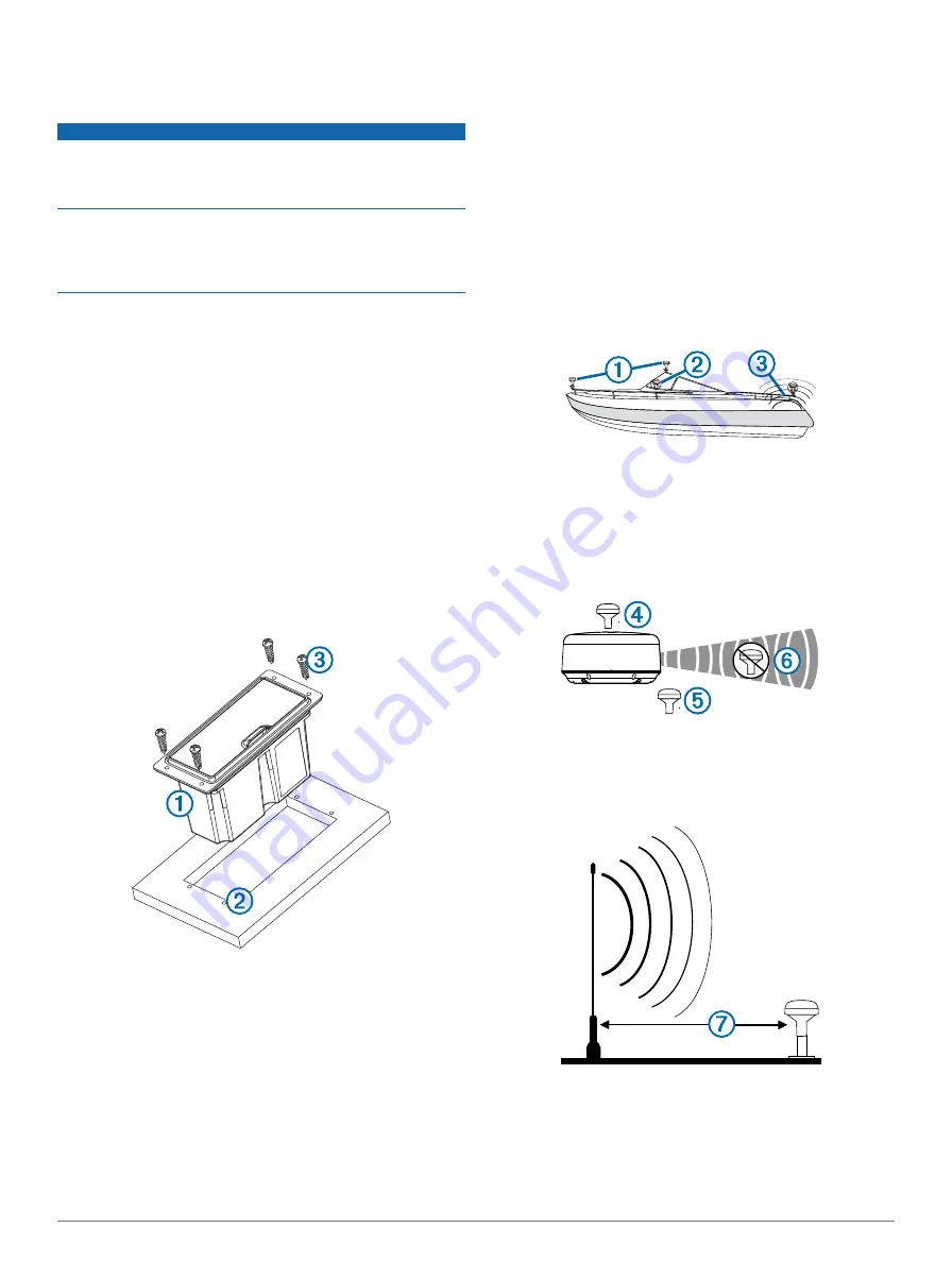
Antenna Mounting Considerations
You can mount the antenna on a flat surface, install it under
fiberglass, or attach it to a standard 1 in. OD, 14 threads per
inch, pipe-threaded pole (not included). You can route the cable
outside of the pole or through the pole. For optimal
performance, consider these guidelines when selecting the
antenna mounting location.
• To avoid interference with a magnetic compass, the antenna
should not be mounted closer to a compass than the
compass-safe distance value listed in the product
specifications.
• To ensure the best reception, the antenna should be
mounted in a location that has a clear, unobstructed view of
the sky in all directions
À
.
• The antenna should not be mounted where it is shaded by
the superstructure of the boat
Á
, a radome antenna, or the
mast.
• The antenna should not be mounted near the engine or other
sources of Electromagnetic Interference (EMI)
Â
.
• If a radar is present, the antenna should be mounted above
the path of the radar
Ã
. If necessary, the antenna may be
mounted below the path of the radar
Ä
.
• The antenna should not be mounted directly in the path of
the radar
Å
.
• The antenna should be mounted at least 3 ft. (1 m) away
from (preferably above) the path of a radar beam or a VHF
radio antenna
Æ
.
• On a sailboat, to prevent inaccurate speed readings caused
by excessive heeling, the antenna should not be mounted
high on the mast.
• The antenna provides more-stable readings when located
nearer to water level.
3


