


Testing the Mounting Location
1
Temporarily secure the antenna in the preferred mounting
location and test it for correct operation.
2
If you experience interference with other electronics, move
the antenna to a different location, and test it again.
3
Repeat steps 1–2 until the antenna operates correctly.
4
Permanently mount the antenna.
Surface Mounting the Antenna
NOTICE
If you are mounting the bracket on fiberglass with screws, it is
recommended to use a countersink bit to drill a clearance
counterbore through only the top gel-coat layer. This will help to
avoid any cracking in the gel-coat layer when the screws are
tightened.
Stainless-steel screws may bind when screwed into fiberglass
and overtightened. Garmin recommends applying an anti-
galling, stainless anti-seize lubricant to the screws before
installing them.
Before you permanently mount the antenna, you must test the
mounting location for correct operation (
1
Using the surface-mount bracket
À
as your mounting
template, mark the three pilot-hole locations and trace the
cable-hole in the center of the bracket.
2
Set the surface-mount bracket aside.
Do not drill through the bracket.
3
Drill the three
1
/
8
in. (3.2 mm) pilot holes.
4
Use a 1 in. (25 mm) hole saw to cut the cable hole in the
center.
5
Place the seal pad
Á
on the bottom of the surface-mount
bracket, aligning the screw holes.
6
Use the included M4 screws to secure the surface-mount
bracket to the mounting surface.
7
Route the cable
Â
through the 1 in. (25 mm) hole and
connect it to the antenna.
8
Verify that the large gasket
Ã
is in place on the bottom of the
antenna, place the antenna on the surface-mount bracket,
and twist it clockwise to lock it in place.
9
Secure the antenna to the mounting bracket with the
included M3 set screw
Ä
.
10
Route the cable away from sources of electronic
interference.
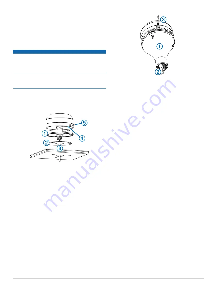
Mounting the Antenna with the Cable Routed Outside the
Pole
Before you permanently mount the antenna, you must test the
mounting location for correct operation (
1
Route the cable through the pole-mount adapter
À
, and
place the cable in the vertical slot
Á
along the base of the
pole-mount adapter.
2
Screw the pole-mount adapter onto a standard 1 in. OD, 14
threads per inch, pipe-threaded pole (not included).
Do not overtighten the adapter on the pole.
3
Connect the cable to the antenna.
4
Place the antenna on the pole-mount adapter and twist it
clockwise to lock it in place.
5
Secure the antenna to the adapter with the included M3 set
screw
Â
.
6
With the antenna installed on the pole mount, fill the
remaining gap in the vertical cable slot with a marine sealant
(optional).
7
Attach the pole to the boat if it is not already attached.
8
Route the cable away from sources of electronic
interference.
Mounting the Antenna with the Cable Routed Through the
Pole
Before you permanently mount the antenna, you must test the
mounting location for correct operation (
).
1
Position a standard 1 in. OD, 14 threads per inch, pipe-
threaded pole (not included) in the selected location, and
mark the approximate center of the pole.
2
Drill a hole using a ¾ in. (19 mm) drill bit for the cable to
pass through.
3
Fasten the pole to the boat.
4
Thread the pole-mount adapter onto the pole.
Do not overtighten the adapter.
5
Route the cable through the pole and connect it to the
antenna.
6
Place the antenna on the pole-mount adapter and twist it
clockwise to lock it in place.
7
Secure the antenna to the adapter with the included M3 set
screw
À
.
4


