


8
With the antenna installed on the pole mount, fill the vertical
cable slot
Á
with a marine sealant (optional).
9
Route the cable away from sources of electronic
interference.
Mounting the Antenna Under the Deck
NOTICE
Before attaching the under-deck mounting bracket to the
surface, verify that the supplied screws will not penetrate the
surface. If the supplied screws are too long, you must purchase
surface-appropriate screws to complete the installation.
Before you permanently mount the antenna, you must test the
mounting location for correct operation (
Because the antenna cannot acquire signals through metal, it
must be mounted under a fiberglass surface only.
1
Place the adhesive pads
À
on the under-deck mounting
bracket
Á
.
2
Place the antenna in the under-deck mounting bracket.
3
Adhere the under-deck mounting bracket to the mounting
surface.
4
Secure the under-deck mounting bracket to the mounting
surface with screws.
5
Connect the cable to the antenna
Â
.
6
Route the cable away from sources of electronic
interference.
Cable and Connection Considerations
NOTICE
A blue rubber seal is included for each DVI port on the device.
This seal must be installed between each DVI port and DVI-
cable connector to avoid damage to the connectors.
• For easer cable routing, the power, NMEA
®
0183, and
Garmin Marine Network cables are packaged without the
locking rings installed. You should route the cables before
you install the locking rings.
• After connecting a locking ring to a cable, make sure the ring
is securely connected and the o-ring is in place so the power
or data connection remains secure.
• The device should be connected to the same power source
as the card reader. If this is not possible, the devices must
be connected to the same ground.
Station Connection Considerations
This device can be set up in conjunction with other compatible
Garmin devices to work together as a station. When planning
stations on your boat, observe these considerations.
• Devices prior to the GPSMAP 8000 series and GPSMAP
8500 cannot be used in a station.
• Although it is not necessary, it is recommended that you
install all of the devices you plan to use in one station near
each other.
• No special connections are necessary to create a station, as
long as all of the devices are connected to the Garmin
).
• Stations are created and modified using the device software.
See the owner's manual provided with the device for more
information.
Connecting to Power
WARNING
When connecting the power cable, do not remove the in-line
fuse holder. To prevent the possibility of injury or product
damage caused by fire or overheating, the appropriate fuse
must be in place as indicated in the product specifications. In
addition, connecting the power cable without the appropriate
fuse in place will void the product warranty.
1
Route the power cable to the power source and to the
device.
2
Connect the red wire to the positive (+) battery terminal, and
connect the black wire to the negative (-) battery terminal.
3
Install the locking ring and o-ring on the end of the power
cable.
4
Connect the power cable to the device by turning the locking
ring clockwise.
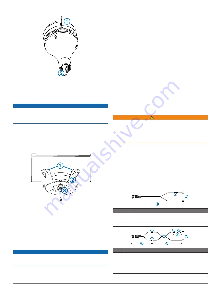
Power Cable Extensions
If necessary, the power cable can be extended using the
appropriate wire gauge for the length of the extension.
Item
Description
À
Fuse
Á
Battery
Â
6 ft. (1.8 m) no extension
Item Description
À
Splice
Á
• 12 AWG (3.31 mm²) extension wire, up to 15 ft. (4.6 m)
• 10 AWG (5.26 mm²) extension wire, up to 23 ft. (11 m)
• 8 AWG (8.36 mm²) extension wire, up to 36 ft. (11 m)
Â
Fuse
Ã
8 in. (20.3 cm)
5


